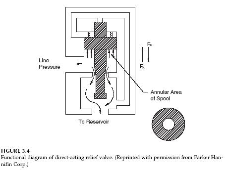
A schematic of a direct-acting relief valve is shown in Fig. 3.4. Pressure acts on the annular area of the valve spool. The hydraulic force is given by
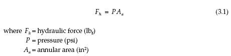
The notation Fs will be used for the spring force. When Fh equals Fs , the valve cracks open, meaning that the spool lifts off its seat and allows fluid to flow to the reservoir. As pressure increases, the spool lifts higher, allowing more flow to bypass to the reservoir. At some pressure level, the total flow bypasses to the reservoir.
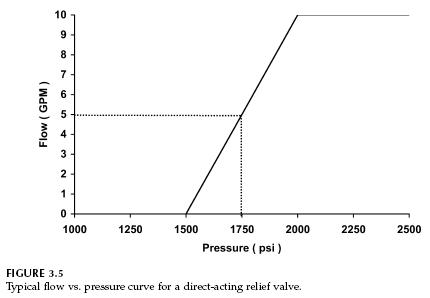
A typical flow vs. pressure curve for a direct-acting relief valve is shown in Fig. 3.5. The valve is set to open at 1500 psi. This pressure is known as the cracking pressure. When pressure reaches 2000 psi, the valve is fully open, and all flow is bypassed to the reservoir; no flow goes to the remainder of the circuit. The 500 psi differential between cracking and full bypass is needed for a direct-acting valve when it has a functional role in flow control in addition to its pressure limiting function. Pilot-operated relief valves have a much lower differential and are used when the sole function of the relief valve is overpressure protection for the circuit.
The characteristics of a direct-acting relief valve can be used in a simple circuit to control the speed of the actuator. In the circuit shown in Fig. 3.6, the flow control valve is simply an adjustable orifice in the circuit. When the flow control valve is partly closed, a pressure drop is created across the valve. Pressure at the relief valve is the sum of the pressure drop across the flow control valve plus the pressure drop across the motor. (For this simple example, pressure drops in the lines are neglected.) To slow the motor, the flow control valve is closed to create enough pressure at the relief valve to cause it to crack open. Part of the pump output now bypasses to the reservoir; thus, flow to the motor is reduced, and the speed decreases.
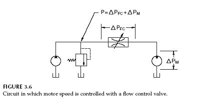
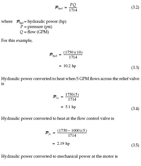
A simple analysis will illustrate the performance of the circuit in Fig. 3.6. Suppose the relief valve has the characteristics shown in Fig. 3.5. The fixed displacement pump is delivering 10 GPM to the motor. The flow control valve is fully open, and the pressure at the relief valve is 1000 psi. To reduce the motor speed to one-half its current value, what pressure drop must be created at the flow control valve?
Flow to the motor must be reduced to 5 GPM to cut the speed by half, which means that 5 GPM must flow across the relief valve. As shown in Fig. 3.5, pressure must rise to 1750 psi before 5 GPM bypasses through the relief valve. Pressure drop across the motor is only 1000 psi; therefore, the required pressure drop across the flow control valve must be 1750 ? 1000 = 750 psi.
No mechanical energy is output at the relief valve; consequently, all the hydraulic energy in the flow across the valve is converted to heat energy. The circuit in Fig. 3.6 is simple but not energy efficient.
It is instructive to calculate the energy flow in this simple circuit. The pump is a fixed-displacement unit; consequently, the delivered flow is constant. (At this time, we neglect that pump leakage increases as pressure increases, and therefore, pump output decreases as pressure increases.) Total hydraulic power delivered by the pump is
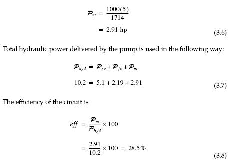
Only 28.5% of the hydraulic power is delivered as mechanical power by the motor. The remainder is converted to heat. Operating temperature of this circuit will be high. Obviously, it is a poor design; however, the analysis does reinforce an important concept in pressure control. Any time there is a pressure drop across a valve and no mechanical power is output, heat is generated and circuit efficiency is reduced. Simple circuits may have a lower initial cost, but the higher operating costs over their design life often offset this advantage.
I can’t believe that anybody trying to understand Pressure, Horse Power, Force, Volume, Time, Area, Distance couldn’t submit a comment. I may not be able to explain it but I’m trying. Brad Taylor
Very informative on an understandable level!