UENR2370-00
30 Page (Dimensions: 39 inches x 28 inches)
ONE POSITION
TWO POSITION
THREE POSITION
VENTED
PRESSURIZED
RETURN ABOVE FLUID LEVEL
RETURN BELOW FLUID LEVEL
LINES CROSSING
LINES JOINING
TWO-WAY
THREE-WAY
FOUR-WAY
SPRING
CONTROL VALVES
RESTRICTION
LINE RESTRICTION
(FIXED)
2-SECTION PUMP
MAIN
AUX.
SPRING
(ADJUSTABLE)
VARIABILITY
LINE RESTRICTION
(VARIABLE)
LINE RESTRICTION
VARIABLE and PRESSURE
COMPENSATED
PRESSURE
COMPENSATION
PUMP: VARIABLE and
PRESSURE COMPENSATED
ENERGY TRIANGLES
HYDRAULIC PNEUMATIC
MEASUREMENT
PRESSURE
TEMPERATURE
FLOW
ROTATING SHAFTS
UNIDIRECTIONAL BIDIRECTIONAL
PUSH-PULL LEVER PEDALGENERAL MANUAL PUSH BUTTON SPRING
MANUAL CONTROL SYMBOLS
HYDRAULIC MOTORS
FIXED
DISPLACEMENT
VARIABLE DISPLACEMENT
NON-COMPENSATED
UNIDIRECTIONAL
BIDIRECTIONAL
HYDRAULIC PUMPS
FLUID STORAGE RESERVOIRS
CROSSING AND JOINING LINES
VALVE ENVELOPES
VALVE PORTS
BASIC COMPONENT SYMBOLS
FLUID CONDITIONER
PUMP or MOTOR
FLUID POWER SYMBOLS
FIXED
DISPLACEMENT
VARIABLE DISPLACEMENT
NON-COMPENSATED
UNIDIRECTIONAL
BIDIRECTIONAL
VALVES
PILOT CONTROL SYMBOLS
RELEASED PRESSURE
EXTERNAL RETURN
INTERNAL RETURN
REMOTE SUPPLY PRESSURE
SIMPLIFIED
COMPLETE
INTERNAL
SUPPLY PRESSURE
ACCUMULATORS
SPRING LOADED
GAS CHARGED
SOLENOID
or MANUAL
SOLENOID
and PILOT
SOLENOID and
PILOT or MANUAL
COMBINATION CONTROLS
SOLENOID
SERVO
THERMAL
DETENT
HYDRAULIC AND PNEUMATIC CYLINDERS
DOUBLE ACTING
SINGLE ACTING
BASIC
SYMBOL
SPRING
LOADED
CHECK VALVES
TWO
POSITION
INFINITE
POSITIONING
FLOW IN ONE
DIRECTION
FLOW ALLOWED IN
EITHER DIRECTION
THREE
POSITION
CROSS
FLOW
PARALLEL
FLOW
INTERNAL PASSAGEWAYS
NORMAL POSITION
AB
PT
AB
PT
SHIFTED POSITION
INFINITE POSITION
CONTROL VALVES
ATTACHMENT
MANUAL SHUTOFF
SHUTTLE PILOT
CONTROLLED
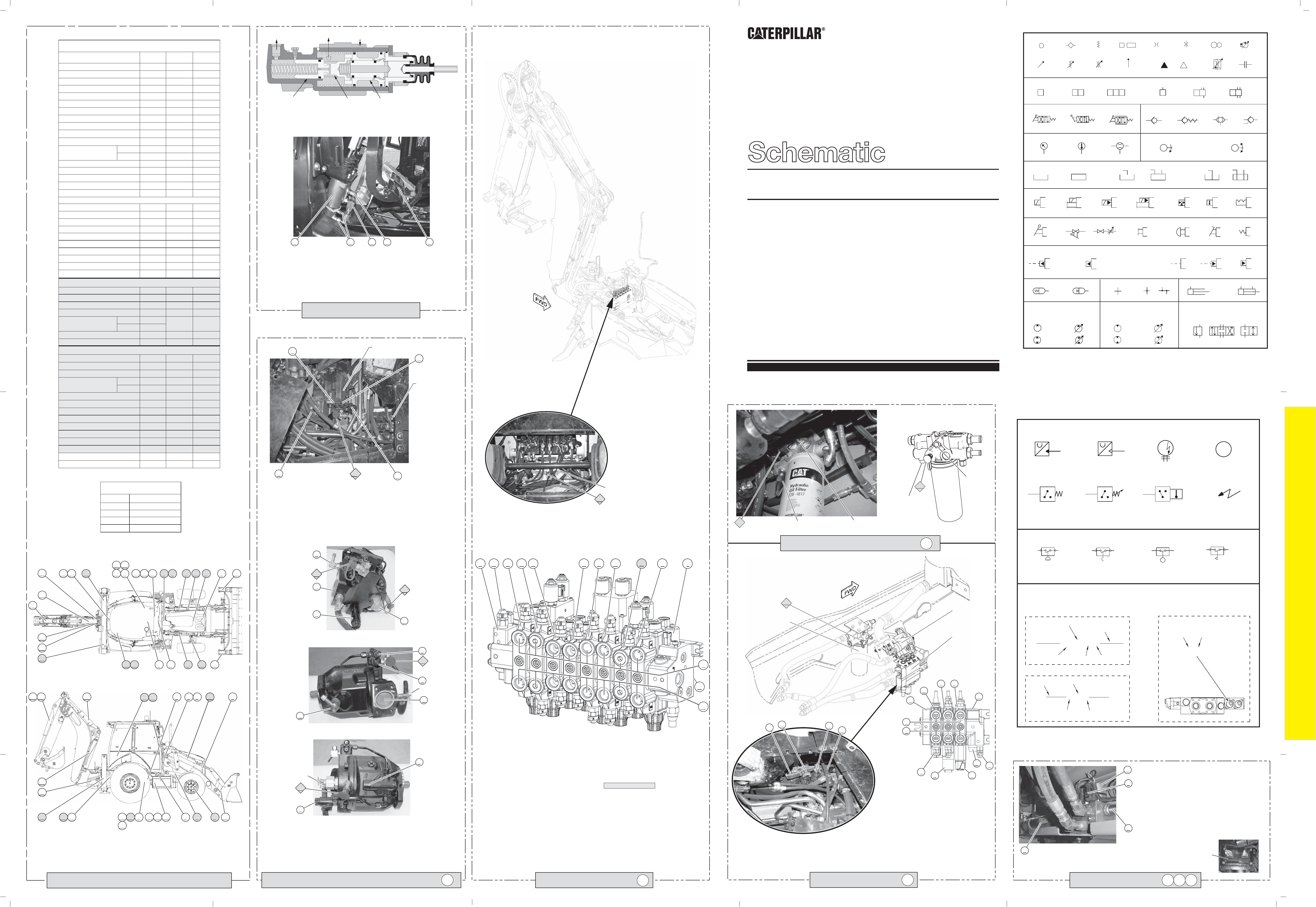
Hydraulic Symbols (Electrical)
Electrical Symbols Table
325-AG135 PK-14
Circuit Identification
Number
Wire Color
Wire Gauge
Harness identification code
This example indicates
wire 135 in harness "AG".
325-PK-14
Wire Gauge
Wire Color
Circuit Number
Identification
Wire Number Identification Codes
Current Standard
Previous Standard
Electrical Schematic Example
Hydraulic Schematic Example
325-PK
Wire Color
Circuit Number
Identification
B
A
Wire
Wire
(EXAMPLE VALVE)
Current Standard
Transducer
(Fluid)
Transducer
(Gas / Air)
G
Generator
Electrical Wire
Pressure Switch
M
Electric Motor
Pressure Switch
(Adjustable)
Temperature Switch
T
Pressure
Symbol
Temperature
Symbol
Level
Symbol
Flow
Symbol
Electrical Symbols (Electrical)
Center Pivot
UENR2370
November 2012
450F Backhoe Loader
Hydraulic System
HJR1-UP
©
2012 Caterpillar, All Rights Reserved
Printed in U.S.A.
Left Hand
Right Hand
Left Hand
Right Hand
Description
1PUMP GP. (Primary)
269-9336
2PUMP GP. (Secondary)
280-7873
4TANK GROUP
245-0169
5COOLER
N/A
6FILTER
359-7232
7HMU
270-1590
8STEER CYLNDER
9
LIFT CYLNDER
10TILT CYLNDER
375-0716
11MP BUCKET CYLNDER (OPT)
12A
STABILIZER CYLINDERS
375-0721
12B
375-0722
13BOOM CYLINDER 375-0723
14STICK CYLNDER 375-0718
15SWING CYLNDER
297-4896
16BUCKET CYLNDER
375-0719
17E-STICK CYLNDER (OPT).
375-0720
18PILOT - LEVER W/DTNT & SWTCH
359-7248
19PILOT
267-2758
22ACCUMULATOR
226-0420
23RIDE CNTRL VALVE (OPT)
245-8780
24RIDE CNTRL ACCMLTR (OPT)
345-3672
25RIDE CNTR PRES. SWTCH (OPT)
304-5696
26TEMP. SENSOR
246-4297
27DIFF. PRES. SWITCH
134-0404
2 BANK
271-0512
3 BANK
271-0513
28AINLET SECTION
343-7137
28BLIFT SECTION
271-0521
28CTILT SECTION
271-0522
28DAUX SECTION
271-0523
28EOUTLET MANIFOLD
269-1079
7 BANK
271-0527
8 BANK
271-0528
29AINLET SECTION
341-4726
29B
STABILIZER SECTION
271-0541
29CAUX SECTION
271-0547
29DBOOM SECTION
271-0542
29ESTICK SECTION
341-8185
29FSWING SECTION
271-0544
29GBUCKET SECTION
271-0545
29HE-STICK SECTION
271-0546
29JOUTLET MANIFOLD
29KPATTERN SWITCHING VALVE
299-9072
21VALVE GP - CUSHION RELIEF
283-6331
30VALVE GP - RELIEF
260-3022
20MANIFOLD - PILOT
268-0094
226-5540
238-5285
375-0717
COMPONENT LIST (PILOT)
3HYDRAULIC TANK
272-0008
2 BANK
3 BANK
271-0522
271-0539
31PRESSURE REUDCING VALVE
300-0430
Machine
Location
Part
Number
Schematic
Location
B-4
B-3
A-3
A-3
B-2
A-5
A-6
C-8
B-8
B-8
F-3
F-7
F-6
F-5
F-5
F-4
F-4
C-5
C-4
E-7
D-8
D-8
D-8
B-3
B-3
C-7
C-7
B-7
B-7
28E
E-7
E-3
E-6
E-6
E-5
E-5
E-4
E-3
E-2
E-5
F-4
E-2
C-6
A-3
E-7
VALVE GROUP ( 2-BANK)
LOADER VALVE (ST)
BACKHOE VALVE
28
28
A-7, C-7
A-7, C-7
29
29
F-7, F-2
F-7, F-2
29B
271-0541
E-7
6 5
7
3
1
8
9
9
10
10
11
11
12
12
13
14
15
14
16
23242528
29 22
19
18
27 26
4
3
1
6 7
5
89
10
11
12
14
13
16
15
17
2324252829
22
19
18
27
26
4
A
B
E
F
D
C
T2
T1
G
D
E
C
T2
T1
A
B
T2
C
H
A BE D C
A B C D E F
G
H
I
J
K
L
M
N
T3
E
DC
B
A
F
B
C
D
J
K
M
P
R
N
E
SOS
SOS
B
A
C
D
COMPONENT LOCATIONS
3
1
67
6
5
5
7
3
1
8
8
9
9
9
10
10
10
11
11
11
12
12
12
14
13
13
14
16
15
15
14
17
16
23
232425
242528
28
29
Tap Description
T1 Pump Discharge
T2 Load Sense
SOS Oil Sampling
TAP LOCATIONS
(A) Outlet Manifold
(B) Left Stabilizer Control Valve
(C) Extendable Stick Control Valve
(D) Bucket Control Valve
(E) Swing Control Valve
(F) Stick Control Valve
(G) Boom Control Valve
ABCD EF
G
H
I
BACKHOE VALVE
29
The 450E machines are equipped with a pilot controlled backhoe valve that is visible with the floor plate at the rear
of the cab removed.
This illustration shows a eight bank backhoe valve. The components in the backhoe valve are:
SOS
Implement and
Steering Pump
HYDRAULIC OIL FILTER
SOS
Filter Bypass Switch
6
The 450E machines are equipped with a mechanically
controlled loader valve as shown in this illustration.
The loader valve is accessed from below the floor
plate. The loader control valve group contains:
LOADER VALVE
E
28
DC
B
A
Travel at high speeds over rough terrain causes bucket movement. The
optional Ride Control System acts as a shock absorber by absorbing
bucket forces, which stabilize the machine.
The Ride Control System components include; ride control relay (A), ride
control solenoids (B), ride control accumulator (C), and ride control
pressure switch (D).
Two solenoids are now used on the "E" Series machines Ride Control
System.
The Ride Control System, on machines with the optional autoshift
transmission, is controlled by the Machine ECM. The Machine ECM
monitors the position of the ride control switch and determines when to
operate the ride control system.
RIDE CONTROL
B
A
C
D
IMPLEMENT / STEERING PUMP
The implement and steering pump on the 450E machines is similar to the "D" Series
machines, but now includes a torque control solenoid (not visible). The torque control solenoid
provides an additional pump setting.
The implement and steering pump is located below the floor plate in the cab. The pump control
valve (H) contains a torque control spool adjustment screw (B) and a flow compensator adjust-
ment screw (A). The adjustment screws and the load sensing pressure tap (T2) are accessible
from the cab.
1
F
View of mechanically controlled loader valve with floor plate removed.
Loader Valve
These illustrations show the implement and steering pump out of the machine. The following compo-
nents are visible:
Torque control adjustment (A), Flow compensator adjustment (B), Load sensing pressure tap (T2),
Inlet port (C), Case drain port (D), Torque control solenoid (E), Discharge pressure tap (T1), Torque
limiter (F), Outlet port (G)
B
C
D
THREE BANK VALVE:
J
K
M
P
R
N
E
G
A
B
E
F
D
C
D
E
C
T2
T1
T2
T1
The 450E machines are equipped with hydraulically assisted master cylinders, which decreases the
amount of pedal effort when braking. This illustration shows the boosted brakes valve group, which uses
oil from the pilot accumulator to add boost to the master cylinder. The hydraulic force multiplies the pedal
effort so the operator can get more braking force with less effort.
The brake boost valves are connected to the master cylinder (A) at each brake pedal (B). Oil enters
the master cylinder through the supply hose (C) and exits the master cylinder through the return hose
(D). The oil flows to the service brakes through the hoses (E) at the bottom of the master cylinder.
The master cylinders can be removed from the machine from inside the operator's compartment.
This illustration shows a sectional view of the boosted brake valve group. When the brake pedal is
depressed, the boost brake valve moves to the left and inlet oil from the pilot manifold is directed
to the master cylinder.
BOOSTED BRAKES
J
K
Drain
EIGHT BANK VALVE (PILOT OPERATED)
For other bank valve configurations see KENR5488 (Specifications Manual).
T3
The pilot manifold can also be
accessed with the floor plate
removed. The pilot pressure tap
(T3) is located on the pilot mani-
fold. The pilot manifold routes pilot
oil to and from the loader and
backhoe pilot control valves.
Pilot Manifold
View of pilot controlled backhoe valve with floor plate removed.
The hydraulic oil filter is located below the
machine at the left frame rail. The hydraulic oil
filter bypass switch is mounted to the oil filter
base.
(H) Auxiliary Control Valve
(I) Right Stabilizer Control Valve
(J) Pilot On/Off Solenoid Valve
(K) Inlet Manifold
(L) A Ports
(M) B Ports
(N) Load Signal Relief Valve
(A) Outlet manifold.
(B) Auxiliary control valve.
(J) Makeup and relief valve.
(C) Tilt control valve.
(D) Lift control valve.
(E) Inlet manifold.
(M) Priority Valve.
(F) Load signal relief valve.
(N) Mechanical detent for the
float.
(P) A ports.
(R) B ports.
SOS
ECM
To Wheel
Brake
Boost Brake
Valve
From Pilot
Accumulator
To Tank
Master
Cylinder
Slave
Cylinder
ABEDC
T3 Pilot Pressure
23 24 25
NOTE: Alpha numeric numbers are represented by the number only on the machine views.
22
29
22
19
19
18
18
27 26
27
26
Hydraulic Oil Filter
Temp Sensor
Filter Bypass
Switch
Temp Sensor
L
M
Implement and
Steering Pump
A
B
T2
C
Loader Valve
H
Drain
N
(K) Magnetic detent for return
to dig function.
For other bank valve configurations see KENR5488 (Specifications Manual).
4
4
Note: The auxiliary Control Valve (H) is not avalible on the optional seven bank valve.
UENR2370-00
30 Page, (Dimensions: 39 inches x 28 inches)
12345678
A
B
C
D
E
F
12345678
A
B
C
D
E
F
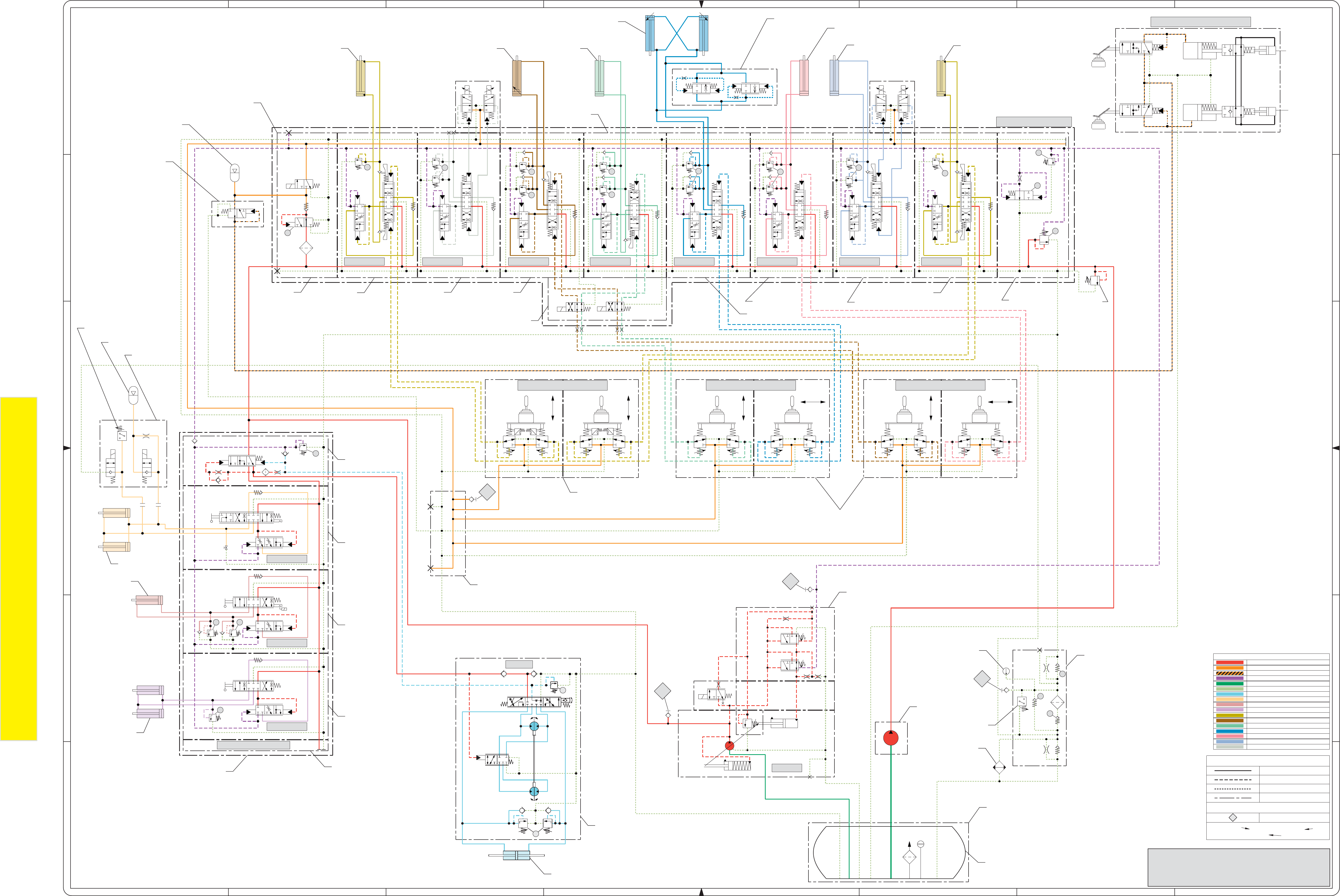
DRAIN / RETURN LINE
HYDRAULIC CIRCUIT COLOR DESCRIPTIONS
IMPLEMENT and STEERING PUMP CIRCUIT
SWING CYLINDER CIRCUIT
STEERING CYLINDER CIRCUIT
PILOT OIL CIRCUIT
BUCKET CYLINDER CIRCUIT
STICK CYLINDER CIRCUIT
LOAD SENSE CIRCUIT
SUPPLY LINE
AUXILIARY CIRCUIT (BACKHOE VALVE)
E-STICK CYLINDER CIRCUIT
BOOM CYLINDER CIRCUIT
STABILIZER CYLINDER CIRCUIT
BOOSTED BRAKE OIL CIRCUIT
LIFT CYLINDER CIRCUIT
TILT CYLINDER CIRCUIT
AUXILIARY CIRCUIT (LOADER VALVE)
450F BACKHOE LOADERS HYDRAULIC SCHEMATIC
MEDIA NUMBER: UENR2370
PART #: 417-3441 CHG00
Components are shown installed on a fully operable machine with the key and engine off.
Refer to the appropriate Service Manual for Troubleshooting, Specifications and Systems Operations
LINE PATTERNS
Drain / Return Lines
Component Group
Pilot / Load Sensing Pressure
Pressure Line
CALLOUTS
Taps (Pressure, Sampling, Sensor - by letter)
YY
(52) VALVE GP - CONTROL
138-1234
Callout Number
(Machine Location from
Component Locations Table)
Component
Name
Part Number
STAB RH BOOM STICK SWING BUCKET E-STICK STAB LH
PUMP
BACKHOE VALVE
AUX.
TILT
LIFT
LOADER VALVE
LEFT JOYSTICK RIGHT JOYSTICK
STABILIZER JOYSTICK
BOOSTED BRAKES (REF)
BS
BT
LEFT
BRAKE
PEDAL
RIGHT
BRAKE
PEDAL
TO REAR AXLE
LEFT WHEEL BRAKE
TO REAR AXLE
RIGHT WHEEL BRAKE
DEL
T3
T2
T1
SOS
AUX.
P16
P17
P18
P2
P1
P20
P7
P14
P8
P13
P11
P12
P10
P9
P15
P7
PR1
P6
P5
P4
P1
HMU
P3
P19
(1) Pump Gp. (Primary):
(2) Pump Gp - Secondary:
(3) Hydraulic Tank:
(4) Tank Group:
(5) Cooler: N/A
(6) Filter:
(26) Temp. Sensor:
(27) Diff. Pres. Switch:
(19) Pilot:
(8) Steer Cylinder:
(7) HMU:
(28) Loader Vlave (2 Bank):
(11) MP Bucket Cylinders OPT:
(10) Tilt Cylinder:
(9) Lift Cylinders:
(25) Ride Cntrl.
Pres. Switch (Opt.):
(24) Ride Cntrl. Accmltr
(Opt):
(23) Ride Cntrl. Valve
(Opt):
(28E) Outlet Manifold:
(28D) AUX Section:
(28C) Tilt Section:
(28B) Lift Section:
(28A) Inlet Section:
(29A) Inlet Section:
(29B) Stabilizer Section:
(29C) AUX Section:
(29D) Boom Section:
(30) Valve Gp -
Relief:
(29K) Boom Section:
(29F) Swing Section:
(29G) Bucket Section:
(29H) E-Stick Section:
(29B) Stabilizer Section:
(29J) Outlet Manifold:
(29E) Stick Section:
(29) Loader Vlave (7 Bank):
(22) Accumulator:
(31) Press Reducing Valve:
(13) Boom Cylinder:
(12B) RH Stabilizer Cylinder:
(14) Stick Cylinder:
(15) Swing Cylinders:
(17) E-Stick Cylinder:
(16) Bucket Cylinder:
(21) Valve Gp - Cushion Relief:
(12A) LH Stabilizer Cylinder:
(18) Pilot - Lever w/DTNT and Switch:
(20) Pilot - Manifold:
246-4297
359-7232
280-7873
134-0404
245-0169
272-0008
271-0523
269-1079
238-5285
270-1590
271-0512
271-0513
375-0717
375-0716
271-0521
271-0522
343-7137
245-8780
345-3672
304-5696
(29) Loader Vlave (8 Bank):
271-0527
271-0528
226-0420
300-0430
341-4726
271-0541
271-0547
271-0542
299-9072
271-0545
271-0544
271-0546
271-0541
271-0539
260-3022
375-0722
375-0723
341-8185
375-0718
297-4896
283-6331
375-0719
375-0720
375-0721
359-7248
267-2758
269-9336
297-1590
(28) Loader Vlave (3 Bank):
226-5540
