RENR4322-03 VOL 1
24 Page,
Volume 1
RENR4322-03
May 2005
950G Series II and 962G Series II
Hydraulic System
Wheel Loader
©
2005 Caterpillar
All Rights Reserved
Printed in U.S.A.
950G II:
AYL1-UP
AYS1-UP
AXX1-UP
BAA1-UP
962G II:
AXY1-UP
BAB1-UP
BAC1-UP
BAD1-UP
Volume 1: Pilot Hydraulics and HMU Steering
Volume 2: Electrohydraulic and Command Control Steering
950G II:
AYB1-UP
AYD1-UP
AXR1-UP
962G II:
AYE1-UP
AYG1-UP
AXS1-UP
ONE POSITION
TWO POSITION
THREE POSITION
VENTED
PRESSURIZED
RETURN ABOVE FLUID LEVEL
RETURN BELOW FLUID LEVEL
LINES CROSSING
LINES JOINING
TWO-WAY
THREE-WAY
FOUR-WAY
SPRING
CONTROL VALVES
RESTRICTION
LINE RESTRICTION
(FIXED)
2-SECTION PUMP
MAIN
AUX.
SPRING
(ADJUSTABLE)
VARIABILITY
LINE RESTRICTION
(VARIABLE)
LINE RESTRICTION
VARIABLE and PRESSURE
COMPENSATED
PRESSURE
COMPENSATION
PUMP: VARIABLE and
PRESSURE COMPENSATED
ENERGY TRIANGLES
HYDRAULIC PNEUMATIC
MEASUREMENT
PRESSURE
TEMPERATURE
FLOW
ROTATING SHAFTS
UNIDIRECTIONAL BIDIRECTIONAL
PUSH-PULL LEVER PEDALGENERAL MANUAL PUSH BUTTON SPRING
MANUAL CONTROL SYMBOLS
HYDRAULIC MOTORS
FIXED
DISPLACEMENT
VARIABLE DISPLACEMENT
NON-COMPENSATED
UNIDIRECTIONAL
BIDIRECTIONAL
HYDRAULIC PUMPS
FLUID STORAGE RESERVOIRS
CROSSING AND JOINING LINES
VALVE ENVELOPES
VALVE PORTS
BASIC COMPONENT SYMBOLS
FLUID CONDITIONER
PUMP or MOTOR
FLUID POWER SYMBOLS
FIXED
DISPLACEMENT
VARIABLE DISPLACEMENT
NON-COMPENSATED
UNIDIRECTIONAL
BIDIRECTIONAL
VALVES
PILOT CONTROL SYMBOLS
RELEASED PRESSURE
EXTERNAL RETURN
INTERNAL RETURN
REMOTE SUPPLY PRESSURE
SIMPLIFIED
COMPLETE
INTERNAL
SUPPLY PRESSURE
ACCUMULATORS
SPRING LOADED
GAS CHARGED
SOLENOID
or MANUAL
SOLENOID
and PILOT
SOLENOID and
PILOT or MANUAL
COMBINATION CONTROLS
SOLENOID
SERVO
THERMAL
DETENT
HYDRAULIC AND PNEUMATIC CYLINDERS
DOUBLE ACTING
SINGLE ACTING
BASIC
SYMBOL
SPRING
LOADED
CHECK VALVES
TWO
POSITION
INFINITE
POSITIONING
FLOW IN ONE
DIRECTION
FLOW ALLOWED IN
EITHER DIRECTION
THREE
POSITION
CROSS
FLOW
PARALLEL
FLOW
INTERNAL PASSAGEWAYS
NORMAL POSITION
A B
P T
A B
P T
SHIFTED POSITION
INFINITE POSITION
CONTROL VALVES
ATTACHMENT
MANUAL SHUTOFF
SHUTTLE PILOT
CONTROLLED
Hydraulic Symbols (Electrical)
Electrical Symbols Table
325-AG135 PK-14
Circuit Identification
Number
Wire Color
Wire Gauge
Harness identification code
This example indicates
wire 135 in harness "AG".
325-PK-14
Wire Gauge
Wire Color
Circuit Number
Identification
Wire Number Identification Codes
Current Standard
Previous Standard
Electrical Schematic Example
Hydraulic Schematic Example
325-PK
Wire Color
Circuit Number
Identification
B
A
Wire
Wire
(EXAMPLE VALVE)
Current Standard
Transducer
(Fluid)
Transducer
(Gas / Air)
G
Generator
Electrical Wire
Pressure Switch
M
Electric Motor
Pressure Switch
(Adjustable)
Temperature Switch
T
Pressure
Symbol
Temperature
Symbol
Level
Symbol
Flow
Symbol
Electrical Symbols (Electrical)
9, 10
3
13
AA, BB
5, DD
6, 7, 8
4
11, 12
24, 25, 26, 27, 28, 29, 31, 34, 35, EE
1, 14, 15, 16, 17, 18, 19, 20, 21, 22, 30, 32
23, CC
58, 63, 64
67, 74
49, 54, 55
45, 46, 47, 70, 71, 72, 73
57, 59, 62
68, 69, LL
33, 36, 37, 38, 39, 40, 41, 44, FF, GG
61, 65, 66, 74, HH
48
50, 51, 52, 53, 56, 60, JJ
42, 43
Item
No.
Component
1
2
3
4
5
6
7
8
9
10
11
Schematic
Location
12
13
14
15
16
17
18
19
20
21
22
23
24
25
26
27
28
29
30
31
32
33
34
A3
A7
35
37
38
39
40
41
Tilt Cylinder
Auxiliary Cylinders @
Lift Cylinders
Front Service Brakes
Left Pedal Assembly
Right Pedal Assembly
Front Service Brakes Accumulator
Rear Service Brakes Accumulator
Parking Brake
Parking Brake Actuator
36
A1
A2
A4
A5
A6
A4
Main Control Valve %
Accumulator (Ride Control) #
Shuttle Valve (Ride Control) #
Line Relief Valve (Tilt Cylinder Head End)
Line Relief Valve (Tilt Cylinder Rod End)
A5
A1
A2
A2
B4
B4
B5
B5
B6
D6
Line Relief Valve (Aux. Cylinder Head End) @
Line Relief Valve (Aux. Cylinder Rod End) @
D6
C1
B7
B7
Pressure Switch (Parking Brake)
B6
Shuttle Valve (Accumulator Charge)
Check Valve (Accumulator Charge)
B5
B5
Proirity Stage Valve (Accumulator Charge)
Rear Service Brakes
Solenoid Valve (Ride Control) #
B4
Check Valve (Ride Control) #
Piloted Operated Check Valve (Float)
Relief Valve (Ride Control Diverter Valve) #
Pressure Switch (Steering Diverter Valve)
D3
Gear Motor (Hydraulic Fan) D2
D6
Secondary Reducing Valve (Pilot Manifold)
D1
Check Valve (Steering Valve) D6
Directional Spool (Steering Valve)
Selector Spool (Steering Valve)
Shuttle Valve (Pilot Manifold) C4
Float Valve (Pilot Manifold) C2
Pilot Control Valve % C4
Connector (Orifice 1.7MM)
Ball Valve (Implement Lockout)
C3
Primary Reducing Valve (Pilot Manifold)
C2
C6
Relief Valve (Accumulator Charge) C5
Strainers (Pilot Manifold)
C1
Main Relief Valve
B6
Spool (Ride Control Diverter Valve)
B4
Accumulator Charge Valve (Braking)
Brake Valve (Parking)
Priority Valve (Brake Accumulator Charge)
Pressure Switch (Service Brake Oil)
Cylinders (Steering)
Brake Control Valve (SERVICE)
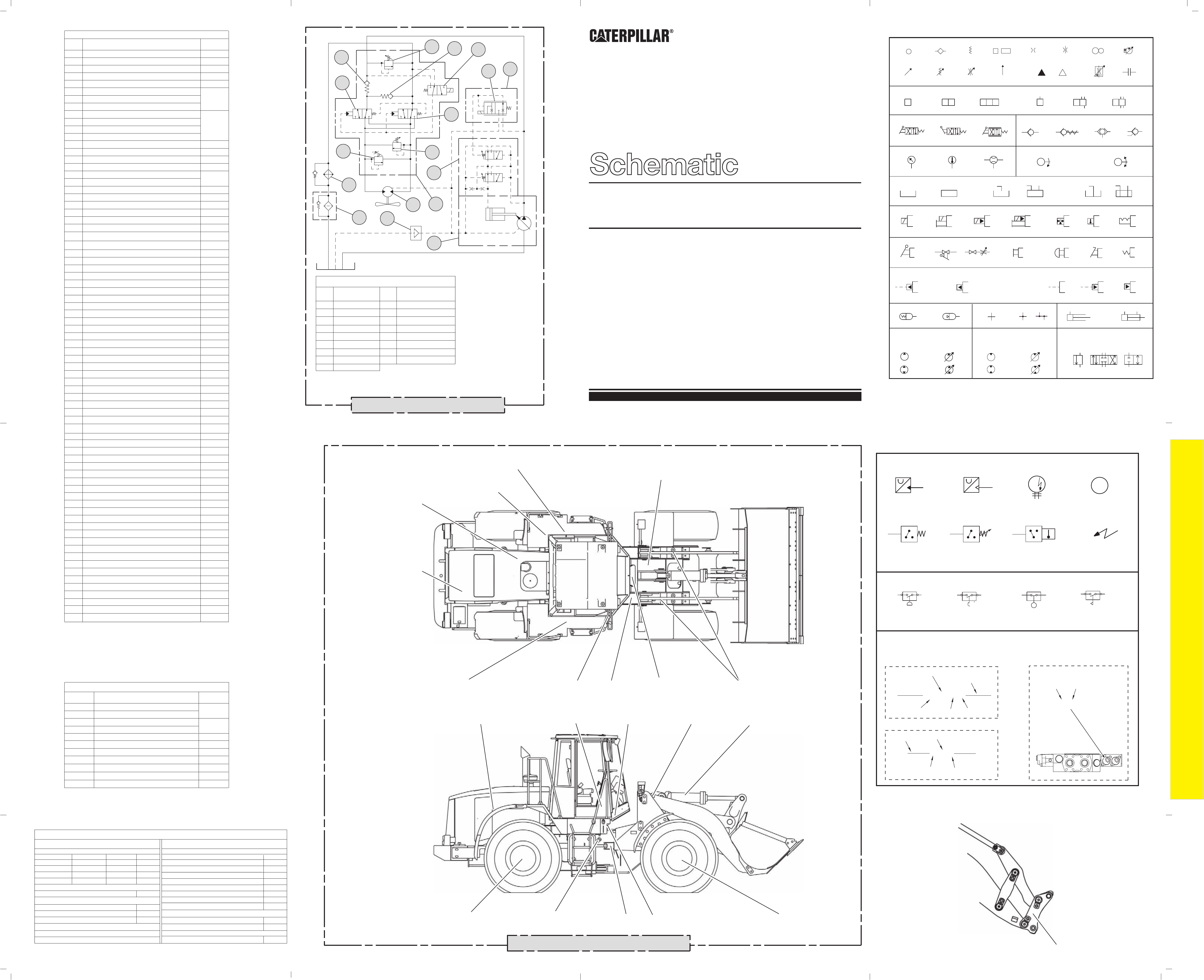
950G II and 962G II Hydraulic Component Locations
45
46
47
44
48
49
50
C3, C4
42
43
Cylinder (Quick Coupler)
Diverter Valve (Quick Coupler)
D6
D6
Schematic
Location
AA
BB
CC
DD
Pressure
Tap
Description
Tilt Cylinder Rod End Pressure
Tilt Cylinder Head End Pressure
Rear Service Brake Pressure
Front Service Brake Pressure
Service Brake Accumulator Pressure
Implement Pilot Pump Pressure
Implement Pump Pressure
Fluid Sampling Valve
Steering Pump Pressure
Steering Signal Pressure
A5
C6
C4
D1
E3
E5
E2
F4
A3
EE
FF
GG
HH
JJ
KK
LL
Pressure Tap Locations
Hydraulic Fan Pump Pressure
* Secondary Steering is an optional attachment.
# Ride Control is an optional attachment.
@ Auxiliary Cylinders are an optional attachment.
% The one stem valve (third function) is an optional attachment field conversion.
The three stem valve is an optional attachment.
The two stem valve is standard.
F3
F3
F6
F5
F4
F1
E1
E2
Relief Valve (Secondary Steering Pump) *
F3
Hydraulic Tank
F5
F4
F3
Strainer (Hydraulic Tank)
F1
Breaker Relief Valve
F1
F1
F3
Oil Filter (Hydraulic)
F2
Pressure Switch (Secondary Steering) *
E4
Piston Pump (Hydraulic Fan)
E2
Solenoid Valve (Hydraulic Fan) E3
Connector (Orifice 1.6MM)
E4
Hydraulic Oil Cooler
E2
Check Valve (Hydraulic Oil Cooler Bypass)
D5
D4
D4
Steering Diverter Valve
Make-up Check Valves (Steering)
Check Valve (Steering)
Crossover Relief Valve (Steering)
Control Valve (Steering)
Metering Pump (Steering)
Secondary Steering Pump and Electric Motor
Pressure and Flow Compensator (Hyd Fan)
Vane Pump (Implement)
Vane Pump (Pilot/Braking)
Steering Neutralizer Valve (Left)
Steering Neutralizer Valve (Right)
Piston Pump (Steering)
Backup Relief Valve (Steering)
51
52
53
54
55
56
57
58
59
60
61
62
63
64
65
66
67
68
69
70
71
72
73
74
75
1
2
3
4
5
6
7
8
9
10
11
12
13
14
15
16
17
Item
No.
Component
950G II and 962G II Hydraulic Components
1
2
3
4
5
6
7
8
9
10
11
12
13
14
15
16
17
Relief Valve
Check Valve
Solenoid Valve
Check Valve
Solenoid Valve
Valve
Diverter Valve
Diverter Valve
Relief Valve
Relief Valve
Valve
Cooler
Piston Motor
Reversing Valve
Filter
Screen
Piston Pump
Reversing Fan Attachment
Item
No.
Component
Reversing Fan Attachment
Note: Installed on the following machines
950G II - AXX and 962G II - AXY
228-8530
Media References
Parts Manual
Systems
Power Train
Engine
SEBP3494
SENR9617
Systems Operation
Testing and Adjusting
RENR4308
RENR4309
RENR4310
Systems Operation (Steering)
RENR4312
RENR4313
950G II AYB
Specifications
Specifications (Steering)
962G II AYE
950G II AYL
962G II BAB
SEBP3495
SEBP3497
SEBP3496
Troubleshooting
Media
Number
950G II AXR
950G II AXX
962G II AXS
962G II AXY
SEBP3352
SEBP3280
SEBP3281
SEBP3285
950G II BAA
962G II BAD
SEBP3492
SEBP3339
Systems (Continued)
Test and Adjusting (Steering)
RENR4314
RENR4315
RENR4316
Specifications (Braking)
Specifications (Machine Systems)
System Operation (Braking)
Testing and Adjusting (Braking)
RENR4317
RENR4362
RENR6042
Operation & Maintenance Manual
English
RENR4318
RENR4319
RENR4320
RENR4321
Specifications (Electrohydraulic/Pilot)
Systems Operation (Electrohydraulic/Pilot)
RENR4324
Schematic (Pilot System)
Schematic (Electrohydraulic System)
SEBU7459
Testing and Adjusting (Hydraulic)
Testing and Adjusting (Electrohydraulic)
Electrical System
Media
Number
MACHINE COMPONENT LOCATIONS
RENR4322-03 VOL 1
24 Page, B/W
A
B
C
D
E
F
1
2
3
4 5
6
7
A
B
C
D
E
F
765
4321
1 2
4
5
AA
BB
CC
DD
6 7 8 9 10 11 123
EE
FF
GG
LL
JJ
M
KK
Implement Pressure
Pilot Pressure
Components
Return Lines
13
14
15
16
17
18
HH
20
21
22
23
24
25 26
27 28
29
30
32
33
35
31
34
36
37
38
38
38 39
40
41
19
49
54 55
58
63
64
65
61
66
66
59
57
67
74
62
44
75
60
68
50
51
52
56
69
70
71
72 73
42
43
45
46
47
48
53
LINEAR PATTERNS
g00984677
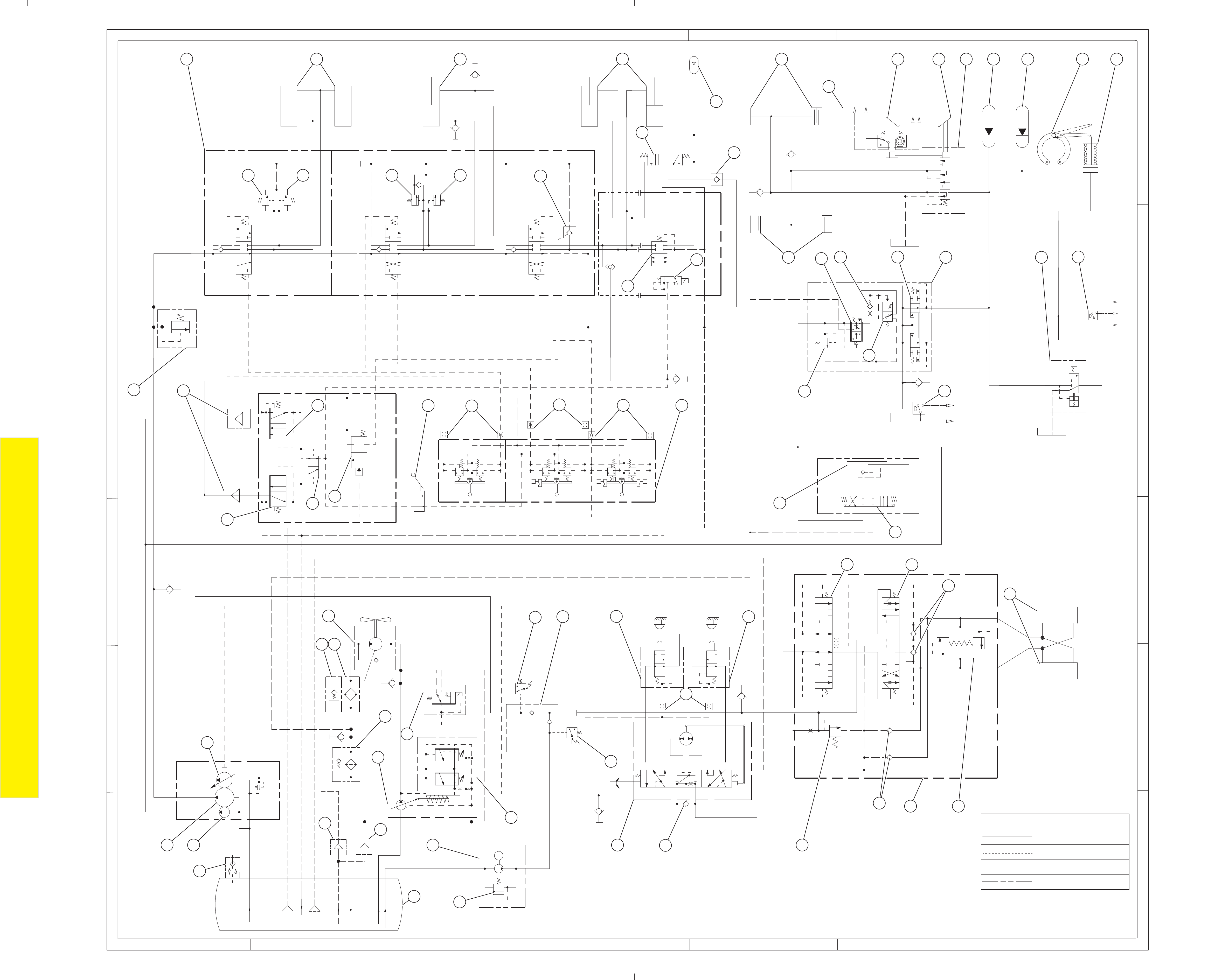
THIS SCHEMATIC IS FOR THE 950G AND 962G SERIES II WHEEL LOADER
PART #: 187-6675 CHG 01
Components are shown installed on a fully operable machine with the key and engine
off and transmission shifter in neutral.
RENR4322-03 VOL 2
24 Page,
Volume 2
RENR4322-03
May 2005
950G Series II and 962G Series II
Hydraulic System
Wheel Loader
©
2005 Caterpillar
All Rights Reserved
Printed in U.S.A.
950G II:
AYL1-UP
AYS1-UP
AXX1-UP
BAA1-UP
962G II:
AXY1-UP
BAB1-UP
BAC1-UP
BAD1-UP
Volume 1: Pilot Hydraulics and HMU Steering
Volume 2: Electrohydraulic and Command Control Steering
950G II:
AYB1-UP
AYD1-UP
AXR1-UP
962G II:
AYE1-UP
AYG1-UP
AXS1-UP
ONE POSITION
TWO POSITION
THREE POSITION
VENTED
PRESSURIZED
RETURN ABOVE FLUID LEVEL
RETURN BELOW FLUID LEVEL
LINES CROSSING
LINES JOINING
TWO-WAY
THREE-WAY
FOUR-WAY
SPRING
CONTROL VALVES
RESTRICTION
LINE RESTRICTION
(FIXED)
2-SECTION PUMP
MAIN
AUX.
SPRING
(ADJUSTABLE)
VARIABILITY
LINE RESTRICTION
(VARIABLE)
LINE RESTRICTION
VARIABLE and PRESSURE
COMPENSATED
PRESSURE
COMPENSATION
PUMP: VARIABLE and
PRESSURE COMPENSATED
ENERGY TRIANGLES
HYDRAULIC PNEUMATIC
MEASUREMENT
PRESSURE
TEMPERATURE
FLOW
ROTATING SHAFTS
UNIDIRECTIONAL BIDIRECTIONAL
PUSH-PULL LEVER PEDALGENERAL MANUAL PUSH BUTTON SPRING
MANUAL CONTROL SYMBOLS
HYDRAULIC MOTORS
FIXED
DISPLACEMENT
VARIABLE DISPLACEMENT
NON-COMPENSATED
UNIDIRECTIONAL
BIDIRECTIONAL
HYDRAULIC PUMPS
FLUID STORAGE RESERVOIRS
CROSSING AND JOINING LINES
VALVE ENVELOPES
VALVE PORTS
BASIC COMPONENT SYMBOLS
FLUID CONDITIONER
PUMP or MOTOR
FLUID POWER SYMBOLS
FIXED
DISPLACEMENT
VARIABLE DISPLACEMENT
NON-COMPENSATED
UNIDIRECTIONAL
BIDIRECTIONAL
VALVES
PILOT CONTROL SYMBOLS
RELEASED PRESSURE
EXTERNAL RETURN
INTERNAL RETURN
REMOTE SUPPLY PRESSURE
SIMPLIFIED
COMPLETE
INTERNAL
SUPPLY PRESSURE
ACCUMULATORS
SPRING LOADED
GAS CHARGED
SOLENOID
or MANUAL
SOLENOID
and PILOT
SOLENOID and
PILOT or MANUAL
COMBINATION CONTROLS
SOLENOID
SERVO
THERMAL
DETENT
HYDRAULIC AND PNEUMATIC CYLINDERS
DOUBLE ACTING
SINGLE ACTING
BASIC
SYMBOL
SPRING
LOADED
CHECK VALVES
TWO
POSITION
INFINITE
POSITIONING
FLOW IN ONE
DIRECTION
FLOW ALLOWED IN
EITHER DIRECTION
THREE
POSITION
CROSS
FLOW
PARALLEL
FLOW
INTERNAL PASSAGEWAYS
NORMAL POSITION
A B
P T
A B
P T
SHIFTED POSITION
INFINITE POSITION
CONTROL VALVES
ATTACHMENT
MANUAL SHUTOFF
SHUTTLE PILOT
CONTROLLED
Hydraulic Symbols (Electrical)
Electrical Symbols Table
325-AG135 PK-14
Circuit Identification
Number
Wire Color
Wire Gauge
Harness identification code
This example indicates
wire 135 in harness "AG".
325-PK-14
Wire Gauge
Wire Color
Circuit Number
Identification
Wire Number Identification Codes
Current Standard
Previous Standard
Electrical Schematic Example
Hydraulic Schematic Example
325-PK
Wire Color
Circuit Number
Identification
B
A
Wire
Wire
(EXAMPLE VALVE)
Current Standard
Transducer
(Fluid)
Transducer
(Gas / Air)
G
Generator
Electrical Wire
Pressure Switch
M
Electric Motor
Pressure Switch
(Adjustable)
Temperature Switch
T
Pressure
Symbol
Temperature
Symbol
Level
Symbol
Flow
Symbol
Electrical Symbols (Electrical)
9, 10
3
AA, BB
5, DD
6, 7, 8
4
23, CC
52
1
2
3
4
5
6
7
8
9
10
11
12
13
14
15
16
17
Item
No.
Component
950G II and 962G II Hydraulic Components
1
2
3
4
5
6
7
8
9
10
11
12
13
14
15
16
17
Relief Valve
Check Valve
Solenoid Valve
Check Valve
Solenoid Valve
Valve
Diverter Valve
Diverter Valve
Relief Valve
Relief Valve
Valve
Cooler
Piston Motor
Reversing Valve
Filter
Screen
Piston Pump
Reversing Fan Attachment
Item
No.
Component
Reversing Fan Attachment
Note: Installed on the following machines
950G II - AXR and 962G II - AXS
228-8530
11, 12
13
14, 15
1, 14, 15, 16, 17, 18, 19, 20, 21, 26, 27, 28, 29, 30, 31,
33, 34, 35, 36, 38, 39, 41, 42, 43, 44, 47, 48, 49, 50
64, 65, 66, RR
70, 73, 74
81, 86
23, 24, 25, 32, 37, 39, 40, 45, 46, MM
59
51, 54, EE, FF, GG, HH, JJ, KK, LL, NN, PP
57, 58, 60, 61, 62, 67, 72, 75
76, 78, 79, 80, 83, SS, WW, XX
77
63, 68, 69, TT
56
55, UU, VV
71, 82, 84, 85
52, 53
Schematic
Location
AA
BB
CC
DD
Tap
Description
Tilt Cylinder Rod End Pressure
Tilt Cylinder Head End Pressure
Rear Service Brake Pressure
Front Service Brake Pressure
Service Brake Accumulator Pressure
EE
FF
GG
HH
JJ
KK
LL
MM
NN
PP
Steering Control Valve
Neutral Pilot Pressure
B2
B3
E2
E6
E3
E4
F4
F6
Fluid Sampling Valve
RR
SS
TT
UU
VV
WW
XX
A3
A5
B1
B2
B3
B4
B5
B6
D1
E1
Hydraulic Fan Pump Pressure
F5
Pilot Pressure (Steering)
Pilot Pressure (Steering )
Pump Pressure (Steering)
Pump Pressure (Implement)
Pump Signal Pressure (Steering)
Pilot Pressure (Steering)
Auxiliary Pilot Pump Pressure (Open)
Auxiliary Pilot Pump Pressure (Close)
Tilt Pilot Pump Pressure (Tiltback)
Tilt Pilot Pump Pressure (Dump)
Lift Pilot Pump Pressure (Lower)
Lift Pilot Pump Pressure (Raise)
Pilot Pressure (Ride Control)
Media References
Parts Manual
Systems
Power Train
Engine
SEBP3494
SENR9617
Systems Operation
Testing and Adjusting
RENR4308
RENR4309
RENR4310
Systems Operation (Steering)
RENR4312
RENR4313
950G II AYB
Specifications
Specifications (Steering)
962G II AYE
950G II AYL
962G II BAB
SEBP3495
SEBP3497
SEBP3496
Troubleshooting
Media
Number
950G II and 962G II Hydraulic Pressure Tap Locations
Pressure
950G II AXR
950G II AXX
962G II AXS
962G II AXY
SEBP3352
SEBP3280
SEBP3281
SEBP3285
950G II BAA
962G II BAD
SEBP3492
SEBP3339
Item
No.
Component
1
2
3
4
5
6
7
8
9
10
11
Schematic
Location
12
13
14
15
16
17
18
19
20
21
22
23
24
25
26
* Secondary Steering is an optional attachment.
A3
# Ride Control is an optional attachment.
Tilt Cylinder
Auxiliary Cylinders @
Lift Cylinders
Left Pedal Assembly
Right Pedal Assembly
Front Service Brakes Accumulator
Rear Service Brakes Accumulator
Parking Brake
Parking Brake Actuator
Ride Control Accumulator #
A1
A2
A4
A5
A6
B5
Main Control Valve %
@ Auxiliary Cylinders are an optional attachment.
% The one stem valve (third function) is an The three stem valve is an optional attachment.The two stem valve is
standard.optional attachment field conversion.
28
29
30
31
32
34
35
36
37
38
39
40
41
42
43
44
45
46
47
50
51
Accumulator (Ride Control) #
Shuttle Valve (Ride Control) #
Line Relief Valve (Aux. Cylinder Head End) @
Line Relief Valve (Aux. Cylinder Rod End) @
Line Relief Valve (Tilt Cylinder Rod End)
Line Relief Valve (Tilt Cylinder Head End)
A6
A6
A7
A7
A7
A7
A5
A5
A5
A1
F1
A2
A3
Pilot Operated Check Valve (Float)
B4
Relief Valve (Ride Control) #
Rear Service Brakes
B5
Pressure Switch (Parking Brake)
B7
Check Valve (Accumulator Charge)
B6
Shuttle Valve (Accumulator Charge)
B6
Solenoid Valve (Ride Control) @
B5
Auxiliary Spool (Main Control Valve) @
Tilt Spool (Main Control Valve)
B2
B1
Lift Spool (Main Control Valve)
B3
Spool (Ride Control) #
B4
Resolver Valve (Dead Engine Lower)
B4
Priority Valve (Accumulator Charge Pilot)
C6
Primary Reducing Valve (Pilot Manifold)
33
C2
Proportional Valve (Tilt Dump)
C2
Proportional Valve (Lift Lower)
C3
Proportional Valve (Auxiliary Lower)
C4
Main Relief Valve
C1
Relief Valve (Accumulator Charge)
C5
Piority Stage Valve (Accumulator Charge)
C6
Accumulator Charging Valve (Braking) C6C6
Strainers (Pilot Manifold) C1
Solenoid Valve (Pilot Pressure Supply)
C2
C1
Float Valve (Pilot Manifold)
C4
Pressure Switch (Service Brakes)
C6
Parking Brake Valve
C7
Proportional Valve (Tilt Tiltback)
C3
48
49
Proportional Valve (Lift Raise) C3
Proportional Valve (Auxiliary Raise)
C4
Secondary Reducing Valve (Pilot Manifold)
D2
Shuttle Valve (Pilot Manifold)
D2
Steering Cylinders
D7
Pilot Valve (Steering) D4
Wheel (Steering Assembly)
D4
Steering Oil Screen Group
D5
Check Valve (Steering Quad)
E5
Brake Control Valve (Service)
Front Service Brakes
E5
Control Valve (Steering)
E5
Crossover Relief Valve (Steering)
E6
Resolver Valve (Steering)
E7
Proportional Valve (Hydraulic Fan)
E3
Check Valve (Hydraulic Oil Cooler Bypass)
E2
Hydraulic Oil Cooler
E2
Gear Motor (Hydraulic Fan)
E2
Check Valves (Steering Valve)
E7
Piston Pump (Hydraulic Fan)
E3
Pressure and Flow Compensator (Hyd Fan)
E3
Piston Pump (Steering)
E1
Oil Filter (Hydraulic)
E2
Shuttle Valve (Steering)
F6
Vane Pump (Implement)
F1Vane Pump (Pilot/Braking)
F1
Resolver Valve (Steering) F4
Diverter Valve (Steering)
F5
Pressure Switch (Secondary Steering) *
F4
Right Neutralizer Valve (Steering)
E5
Left Neutralizer Valve (Steering)
Pressure Reducing Valve (Steering)
F6
Backup Relief Valve (Steering)
F7
F1
Secondary Steering Pump and Electric Motor *
Breaker Relief Valve
F1
Pressure Switch (Steering Pump)
F5
Hydraulic Tank
F1
Strainers (Hydraulic Tank)
F2
Relief Valve (Secondary Steering Pump) *
F4
Ball Valve (Dead Battery, Lift Arm Lower)
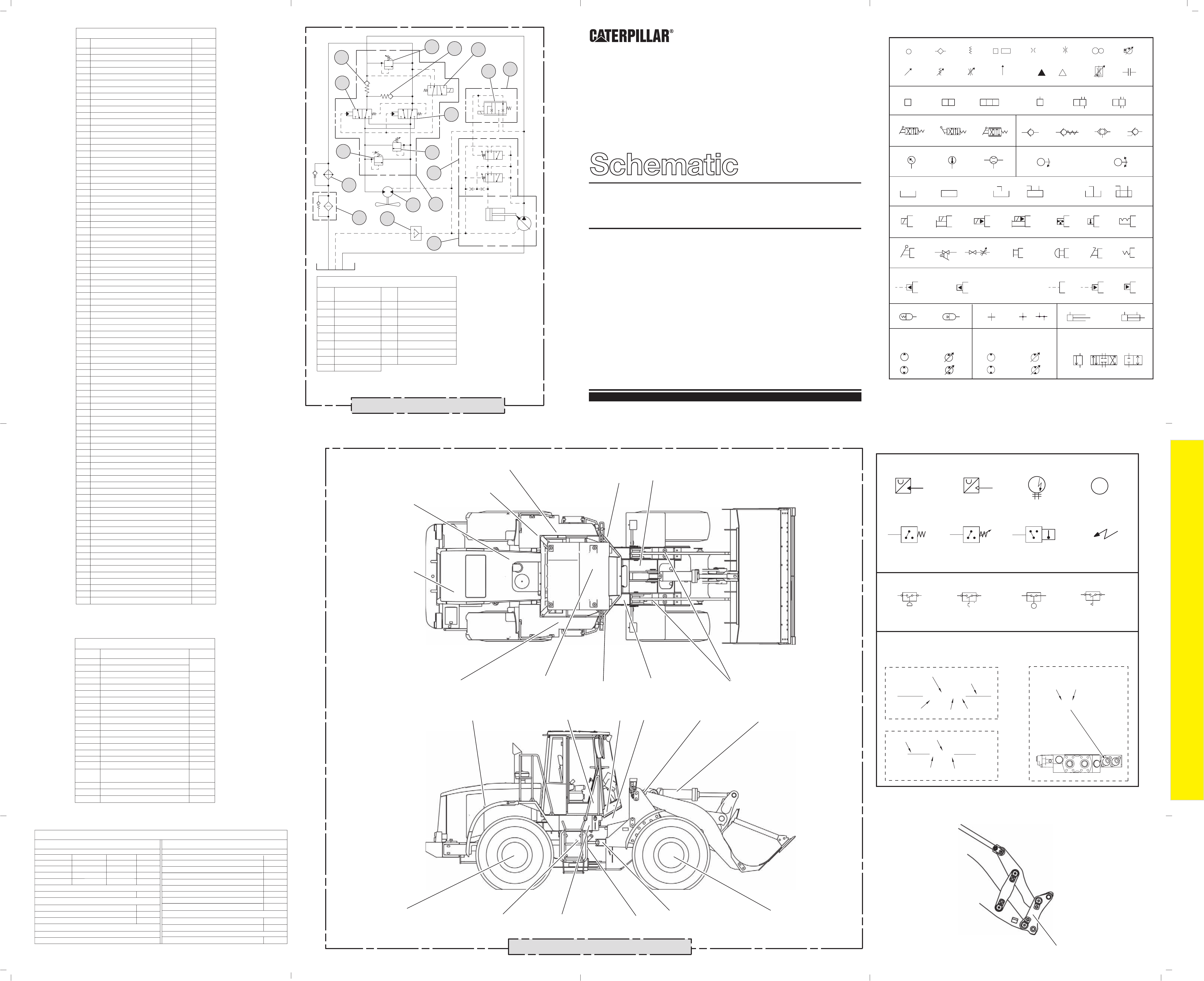
950G II and 962G II Hydraulic Component Locations
54
55
56
57
58
52
53
D6
D6
Cylinder (Quick Coupler)
Diverter Valve (Quick Coupler)
59
60
61
62
63
64
65
66
67
68
69
70
71
72
73
74
75
76
77
78
79
80
81
82
83
84
85
86
27
Chart A
Systems (Continued)
Test and Adjusting (Steering)
RENR4314
RENR4315
RENR4316
Specifications (Braking)
Specifications (Machine Systems)
System Operation (Braking)
Testing and Adjusting (Braking)
RENR4317
RENR4362
RENR6042
Operation & Maintenance Manual
English
RENR4318
RENR4319
RENR4320
RENR4321
Specifications (Electrohydraulic/Pilot)
Systems Operation (Electrohydraulic/Pilot)
RENR4324
Schematic (Pilot System)
Schematic (Electrohydraulic System)
SEBU7459
Testing and Adjusting (Hydraulic)
Testing and Adjusting (Electrohydraulic)
Electrical System
Media
Number
MACHINE COMPONENT LOCATIONS
RENR4322-03 VOL 2
24 Page, B/W
A
B
C
D
E
F
1
2
3
4 5
6
7
A
B
C
D
E
F
G
765
4321
AA
BB
CC
DD
EE FF GG HH JJ
KK LL
MM
NN
PP
RR
TT
UU
VV
SS
WW
M
1
2
3
4
5
6
7
8
9
10
11
12
13
14
15
16 17 1918
20
22
23
25
26
27
28 29 30
31
32
33
34
35
36
37
38
39
40
42
45
41
43
44
50
51
47
48
49
46
XX
24
64
65
66
63
68 69
71
70
73 74
82
84
85
55 56
58 59
75
81
86
83
76 77
78
79
72
61
60
57
62
67
80
52
53
54
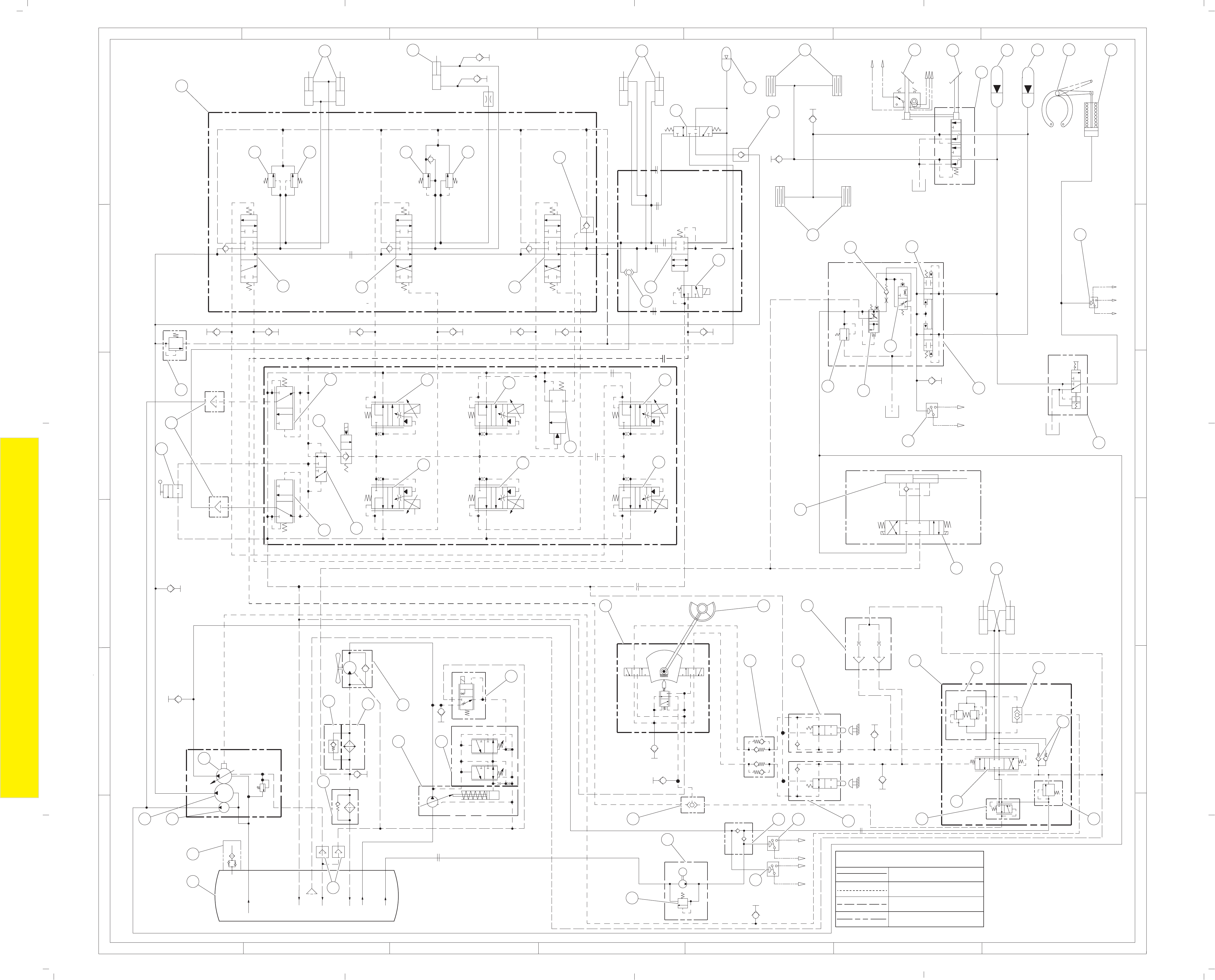
g00986326
Implement Pressure
Pilot Pressure
Components
Return Lines
LINEAR PATTERNS
THIS SCHEMATIC IS FOR THE 950G AND
962G SERIES II WHEEL LOADER
PART #: 187-6675 CHG 01
Components are shown installed on a fully operable machine
with the key and engine off and transmission shifter in neutral.
