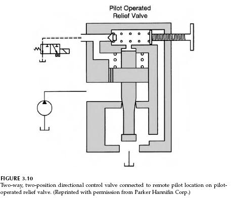
A pilot-operated relief valve can be used to unload the pump at low pressure during periods between work cycles. The schematic in Fig. 3.10 shows a solenoid-actuated directional control valve connected to the remote pilot port on the side of the valve. In the position shown, the port is connected to the reservoir. The pilot spring cavity is vented, and the main relief valve opens at the main spring setting. In the shifted position, the directional control valve blocks the port, and the pilot-operated valve operates as previously described. Repeating the description, when the control valve is shifted to the left (port blocked), the integral pilot relief valve is operational, and the main relief valve acts like a pilot-operated relief valve. In the unactuated position, the port is connected to the reservoir, and the main valve is held closed by the 75 psi spring only. When pressure increases above 75 psi, the valve opens, thus the pump builds only 75 psi pressure during the periods between work cycles.
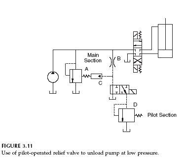
A diagram of a circuit that uses a pilot-operated relief valve to unload the pump at low pressure is shown in Fig. 3.11. The relief valve symbol designated with the letter “A” refers to the main spool of the pilot-operated relief valve. The orifice in the skirt is orifice B, and the symbol designated with letter “C” is a symbol that shows that the valve is held closed with spring pressure and a pilot pressure. The relief valve symbol designated with a letter “D” refers to the pilot stage of the valve (dart held in place with the pilot spring). The circuit operates in the following manner. When the four-way, three-position directional control valve is shifted to extend (or retract) the cylinder, the three-way, two-position directional control valve is simultaneously shifted. The pilot-operated relief valve is thus set to open at the pilot spring setting plus the main spring setting, 1925 + 75 = 2000 psi. When the three-position directional control valve shifts back to the center position, the two-position directional control valve shifts to connect the pilot pressure line to the reservoir. The main relief valve now opens at 75 psi.
When drawing circuit diagrams, a designer will often use a simplified symbol to designate a pilot-operated relief valve. The complete symbol (components A, B, C, and D in Fig. 3.11) is used only when it is needed to explain circuit operation.
A second method for using the pilot-operated relief valve to unload the pump between work cycles is shown in Fig. 3.12. Here, a special directional control valve is used with a fifth port. This port provides a pathway for the pilot line to be connected to the reservoir when the directional control valve is centered. When the directional control valve is shifted, the pilot line is blocked, and the pilot-operated relief valve will not open until the pressure equals the pilot spring pressure plus the main spring pressure.

The circuit in Fig. 3.13 is designed to provide high-pressure relief during extension and low-pressure relief during retraction. (The functional requirements of the circuit are unexplained at this point. The low-pressure relief may be needed to prevent damage or injury, if the workpiece strikes an obstruction during retraction.) Use of the pilot-operated relief valve is similar to the use in Fig. 3.11. The check valve is held in place by high pressure, thus blocking the remote pilot connection on the pilot-operated relief valve. The valve then opens at the high-pressure setting (pilot spring + main spring pressure). During return, the pilot line is connected to the reservoir (as shown in Fig. 3.10); therefore, the valve opens at the low-pressure setting (main spring pressure). It is understood that the low-pressure setting must be high enough to provide the force needed for normal retraction.
