©
2002 Caterpillar
All Rights Reserved
Printed in U.S.A.
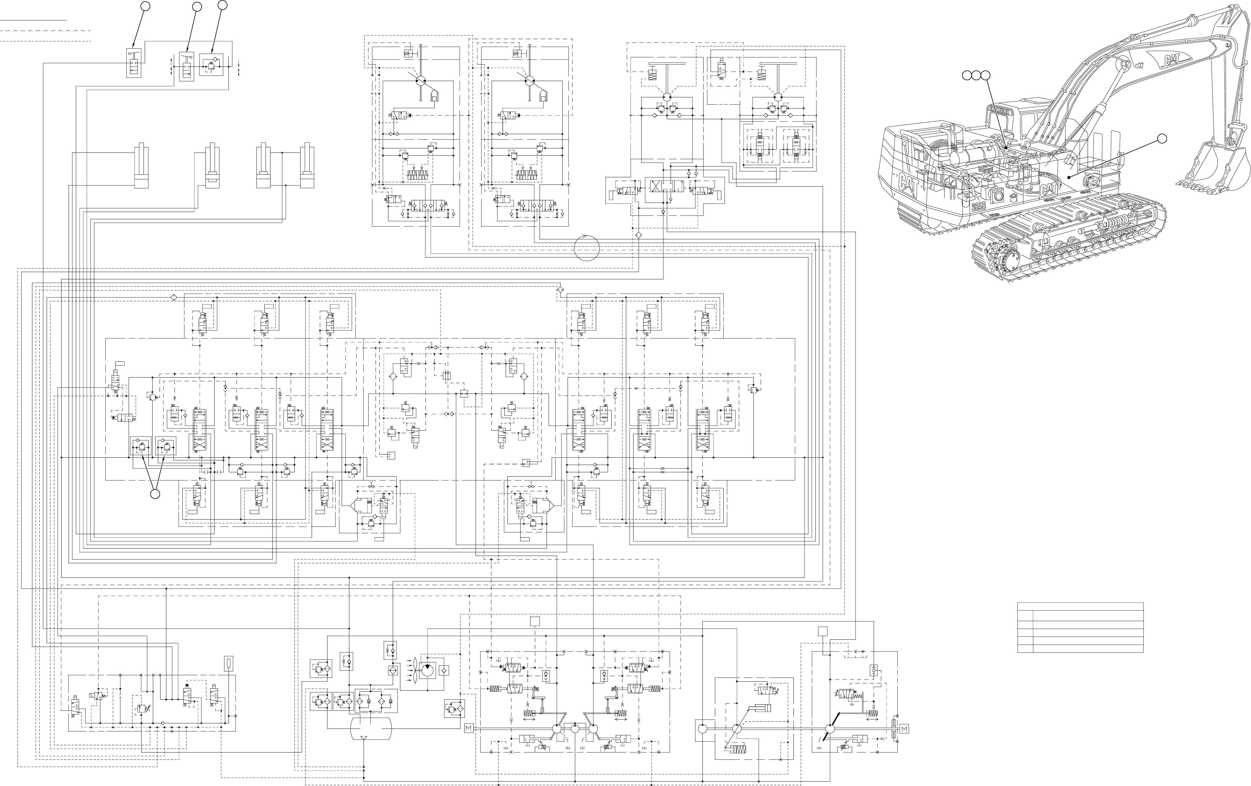
This attachment schematic is to be used in conjunction with the Standard Schematic in this Service Manual.
RENR3703-01
September 2002
365B Excavator
Combined Function, Two Pump Flow
AGD1-235
4XZ1-339
9PZ1-474
9TZ1-530
Hydraulic System - Attachment
R
T1
RIGHT
L'
L'
B' A'
BR
BR
MB
MA
M
MB
A'B'
STICK CYLINDER
LEFT
BUCKET CYLINDER
PR
PG
E
F
SWING
L2
D
L1
Qmax Qmin
T1
LEFT
A'
D
F
E
P
T
M2
M1
B'
B
P1
P2
Dr
A
TRACK
T2
X
T2
BL2
AL2
B
LL1S
PSA3
PSA2
PSA1
PG
PIN
TOUT
DR1
DR2
DR3
Pi5
PAC
Pi3
Pi2
Pi1
Pi4
Pi6
M1
T2T1
R
S
AS
PSA4
DR6
M
G
aR3
aL3
bR3
bL3
aL1
aR1
bL4
aL4
bR1
PF
PR
bL1
P
R1
D1
D2
R2
AL4
BR1
R2
ATT
AR1
BL1
AL1
AR3
BR3
AL3
BL3
RIGHT
S1
DR5
BL4
dR1
bL2
QmaxQmin
B
M2
M2g
A
LS2
LS2g
PS2g
PS2
M2g'M1g'
PS1g
PS1
aL2
R1
STICK
BUCKET
BOOM
TRAVEL TRAVEL
DR4
LS1g
LS1
SA1
M1g
M1
P2
P1
P
)(
)(
M
MA
QminQmax
B
A
PD
P1
P2
2141
REV
FWD
Dr
FWD
2141
REV
DOWN
OPEN
UP
CLOSE
X
OUT
SA2
IN
1
Item
No.
Description
ATTACHMENT COMPONENTS
2
3
4
Ball Valve
Line Relief Valve (One Way)
Line Relief Valves (Two Way)
Ball Valve
1
2
3
BOOM CYLINDERS
4
4
321
PILOT LINE
DRAIN LINE
This Attachment Schematic is intended to
be used in conjunction with the Standard
Hydraulic Schematic in this Service Manual.
Hydraulic Schematic
MAIN CONNECTOR LINE
140-0720
f06539
