©
2002 Caterpillar
All Rights Reserved
Printed in U.S.A.
RENR2172-02
May 2002
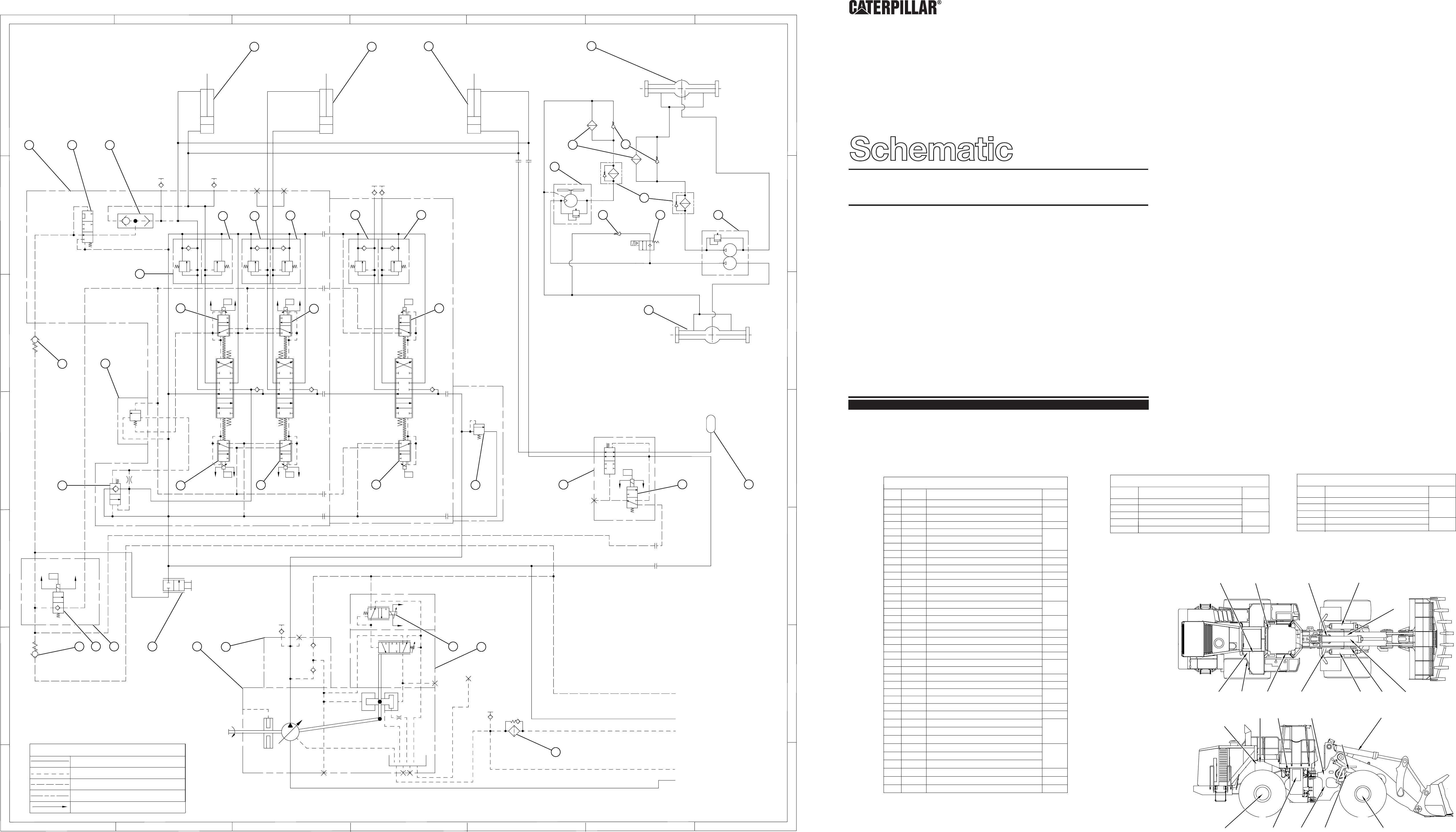
988G Wheel Loader
Hydraulic System
BNH1-Up
2TW1-Up
Item
No.
Component
Schematic
Location
Pressure
Tap
Description
A
B
C
D
E
F
G
1
2
3
4 5
B
C
D
E
F
G
5
4
321
6
7
6
A
7
Schematic
Location
AXLE OIL COOLER SYSTEM SCHEMATIC
988G Hydraulic Component Locations
No.
Part
184-1638-02
PUMP CASE
AIR PURGE
PUMP CASE
FILL PORT
RIDE
CONTROL
RACK
LOWER
DUMP
RAISE
IMPLEMENT SYSTEM SCHEMATIC
114-5109-5
X1
X2
X3
X4
X5
49 50
51
52
53 54 55
56
57
58
59
60 61
62
63 64 65 66 67
68
69
II
JJ
KK
LL
MM
Schematic
Location
Pressure
Tap
Description
Chart F
988G Supply, Pilot, and Return Lines
Chart E
988G Hydraulic Pressure Tap Locations
X1
X2
X3
X4
X5
Implement Pilot Supply
Implement Return Line
Implement Pump Case Drain
Air Purge Line
Implement Pump Supply
Lift Rod End
Lift Head End
Auxiliary Line Relief
Auxiliary Line Relief
Implement Relief
II
JJ
KK
LL
MM
49
50
51
52
53
54
55
56
57
58
59
60
61
62
63
64
65
66
67
68
69
70
71
72
73
74
75
76
77
78
79
80
81
82
83
84
85
86
87
69
69
70
71
72
73 74
74
74
75
76
77 78
79
Lift Cylinder
Tilt Cylinder
173-8613
152-1644
173-8612
Lift Cylinder
NA
Front Axle
Main Control Valve
6E-4286
Pressure Reducing Valve
4T-1860
Shuttle Valve
173-6753
Brake Oil Cooler
130-9704
Check Valve
178-1602 Brake Oil Cooler Fan Motor
183-6194
Brake Oil Filter
125-9349
Line Relief Valve (Lift Cylinder Head End)
117-0161
Line Relief Valve (Tilt Cylinder Rod End)
117-0160
Line Relief Valve (Tilt Cylinder Head End)
172-5481
Line Relief Valve (Auxiliary)
172-5481
Line Relief Valve (Auxiliary)
9T-5134
Check Valve
149-2610
Solenoid Valve
187-3707
Brake Oil Cooler Pump
117-0161
Line Relief Valve (Lift Cylinder Rod End)
217-6720
Actuator (Lift, Tilt, Auxiliary)
NA
Rear Axle
9T-3096
Check Valve
100-6731
Float Valve
6E-1291
Float Check Valve
217-6719
Actuator (Lift, Tilt, Auxiliary)
117-0159
Main Relief Valve
199-3131
152-8340
219-7983
104-7108
Check Valve
149-2610
Solenoid Valve
151-7455
Pilot On/Off Solenoid Valve
112-1817 Ball Valve (Manual Lower)
219-7225
Implement Pump
175-2791
Implement Pump Shuttle Valve
205-3998
Implement Pump Flow Control Valve
166-4647
Implement Pump Case Drain Filter
195-3739
Implement Pump Solenoid Valve
A3
A4
A6
A1
A5
A6
B5
B6
B2
B3
B4
B6
B7
B2
C2, C3, C4
C6
C1
D1
D2, D3, D4
D5
D6
D7
F1
F2
F4
F5
G5
80
81 82 83
84
85
86
87
B2
B4
E3
F6
G6
65, 66, 70
79
78, 82
52
50
II-LL
53-55
49, 51
60-64
68-72
73-75
80-81
76, 7756-5967MM
83-87
MM
83-87
65, 66, 70
79
78, 82
51 5052
49
II-LL
53-55
60-64
68-72
73-75
80-81
76, 77
67
56-59
Chart D
H717-BR
H716-WH
H714-OR
H716-WH
E920-BR
H716-WH
H716-WH
H713-PK
E919-YL
H716-WH
H716-WH
H707-YL
975-WH
976-OR
Pilot Pressure
LINEAR PATTERNS
Return Lines
Pressure
Components
Denotes Wire Code
212-8712
3. Ride Control is an optional attachment.
1
1
1
2
Ride Control Valve
Ride Control Solenoid Valve
Ride Control Accumulator
3
3
3
For attachments use 212-8721 and 212-8746 main control valves.
1.
2.
Logger machines use 168-6942 and 168-6943 lift cylinders
and 191-3846 tilt cylinder.
F05567
Item
No.
Component
Schematic
Location
Schematic
Location
Pressure
Tap
Description
A
B
C
D
E
F
G
3 4 5
B
C
D
E
F
G
5
4321
6 7 8
6
A
7 8
1
Chart A
2
2
3
4
5
7
8
9
10
11
12
6
Item
No.
Component
AA
BB
1
A7
13
14
15
16
17
18
19
20
21
22
23
24
25
26
27
28
29
30
31
32
33
CC
DD
35
36
37
38
39
40
No.
Part
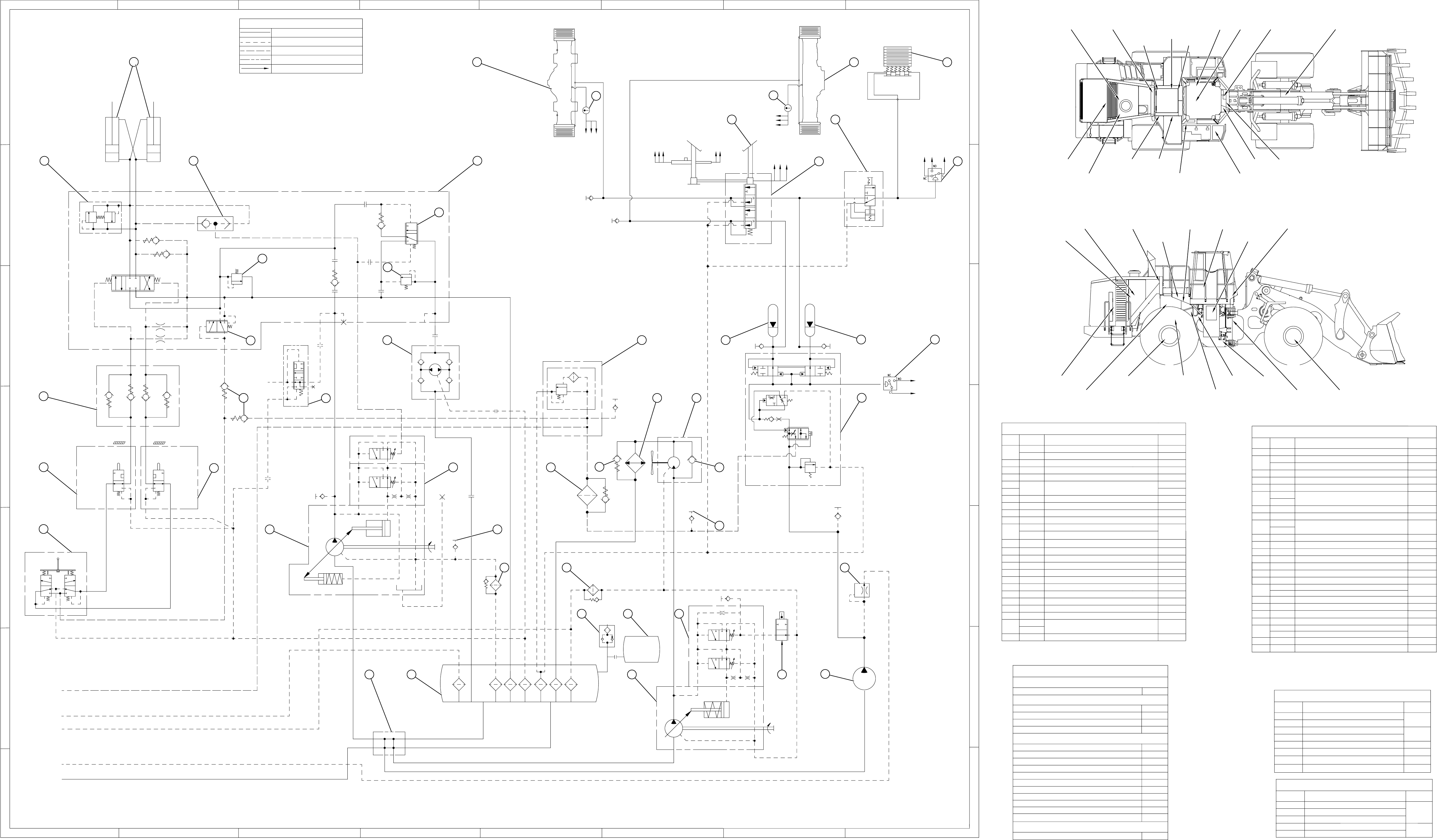
988G Hydraulic Component Locations
No.
Part
Schematic
Location
Chart A
988G Hydraulic Component Locations
BRAKE SCHEMATIC
156-9680-03
18
18
Chart B
988G Pressure Tap Locations
133-8173
Left Cylinder Group
135-3288
Right Cylinder Group
PUMP
CASE
FILL
PORT
X
LEFT
NEUTRALIZER
RIGHT
NEUTRALIZER
SWITCH
1
2
3 4
5
6
AA
Rear Axle
Front Axle
STEERING SCHEMATIC
114-5109-05
7 8
9
10 11
13
14
15
16
17
18
19 20
20 21
22
23
24
25 26
27
28
39
30 31
32
33
34
35
36
37
38 39 40
41 42 43
44 45 46 47
48
NA
NA
4E-8525
Parking Brake
131-0427
Temperature Sensor
169-8258
Foot Brake Control
106-1774
Parking Brake Valve
9T-7419
Relief Valve
4T-1860
Shuttle Valve
133-8608
Steering Valve
200-0866
Tanden Brake Valve
3E-6452
2U-7345
6E-6188
Relief Valve
6E-3986
6E-4286
Pressure Reducing Valve
150-7585
186-6218
Pilot Relief Valve
220-1432
3E-7693
Pressure Switch
149-4617
9T-3096
Check Valve
104-7108
6E-5566
Secondary Steering Selector Valve
164-0058
Cooler
139-6825
213-5268
Gear Motor
Piston Motor
133-7102
Brake Accumulator Charging Valve
146-7571 Right Steering Neutralizer Valve
Left Steering Neutralizer Valve
146-7571
176-7521
176-7520
Pressure and Flow Compensator Valve
115-2129 Oil Filter
6E-1454
9T-3752
Check Valve
34
143-2855 Steering Pilot Valve
153-9624
Steering Pump
Cooler Bypass Valve
196-1172
41
42
43
44
45
46
47
48
NA
8C-3446
166-4647
Oil Filter
166-4647
Oil Filter
3G-8607
Check Valve
9T-0818
Breaker Relief Valve
220-2948
Expansion Tank
191-2929
Pressure and Flow Compensator Valve
152-3870
153-3602
Hydraulic Tank
Fan Drive Pump
152-7202 Thermostatic Valve
177-8924
Brake\Pilot Pump
Schematic
Location
Description
A2
A2
A5
A7
A8
A5
A7
A7
B1
B2
B4
B7
B8
Pressure Switch Parking Brake
B4
C3
C4
C3
C4
C6
C7
Brake Accumulator
C8
D1
D2
D3
D6
D6
D6
D7
D1
D2
D4
D5
D5
D6
E1
E3
E4
E6
E5
E5
E7
E5
E6
E6
F4
F4
F5
F7
F7
EE
FF
GG
HH
Rear Brake Pressure
Front Brake Pressure
Front Service Brake Pressure
Rear Brake Pressure
Steering Pilot Supply
Steering Pump Discharge
Brake Pump Discharge
Fan Drive Pump Discharge
B5
C7
D5
D3
E7
E6
No.
Item
X1
X2
X3
X4
Implement Return Line
Implement Pump Case Drain Line
Implement Signal Pressure Line
Air Purge Line
Implement Pump Supply
X5
G1
F1
Steering Neutralizer Check Valve
BB
CC DD
EE
FF
GG
HH
Air Purge Tap Steering Pump
X1
X2
X3
X4
X5
Pilot Pressure
LINEAR PATTERNS
Return Lines
Pressure
Parts Manual
Systems
Power Train
Systems Operation
Testing and Adjusting
Systems Operation (Steering)
Specifications (Braking)
Specifications (Machine Systems)
Testing and Adjusting (Braking)
Specifications
Specifications (Steering)
Media
Number
Electrical System
Disassembly and Assembly Supplement
Schematic
Parts Book
Components
Denotes Wire Code
Systems Operation (Hydraulics)
Specifications (Hydraulics)
Testing and Adjusting (Hydraulics)
System Schematic (Hydraulics)
Testing and Adjusting (Steering)
988G (BNH, 2TW) MEDIA REFERENCES
Systems Operation (Braking)
RENR3093
RENR3094
RENR3095
RENR3096
RENR3097
RENR3098
RENR3099
RENR2197
RENR2198
RENR2199
RENR2169
RENR2170
RENR2171
RENR2172
RENR2195
RENR6005
Hydraulic Tank Manifold
1, 4
2, 5
3, 6
9-11, 14,
8, 13
12, 21, 27
AA, BB, CC, DD
Hydraulic Oil Sampling Valve
7
20
25, 32
26, 33
38, 39, 41,
22, 28, 29
43, 46, 47, HH
15, 16, 17, 24
19, 31, 37, EE
23, 34, 36
48, FF, GG
30, 35, 40,
42, 44, 45
9-11, 14,
15, 16, 17, 24
20
25, 32
43, 46, 47, HH
48, FF, GG
30, 35, 40,
38, 39, 41,
42, 44, 45
1, 4
22, 28, 29
3, 6
7
23, 34, 36
12, 21, 27
AA, BB, CC, DD
2, 5
19, 31, 37, EE
26, 33
8, 13
SEBP3378
Chart C
988G Supply, Pilot, and Return Lines
12
K983-BU
201-BK
446-PU
K983-BU
201-BK
429-YL
F722-OR
F721-GY
998-BR
102-RD
604-OR
164-WH
202-BK
H722-GN
201-BK
432-PK
C491-PU
G756-YL
202-BK
Position Sensor
Left Brake
Stop Lamp
Switch
Right Brake
Switch
STOP STOP
WARNING
133-8609
Steering Valve with Secondary Steering
Breaker Relief Valve
215-5721
Fan Drive Pump
152-7767
220-0812
F05566
1
1
1
Secondary Steering Diverter Valve
Secondary Steering Pump
Secondary Steering Relief Valve
1
Secondary Steering is an optional attachment.
2
2
Hi ambient package is an optional attachment.
3
3
EU attachment.
3.
2.
1.
