Printed in U.S.A.
All Rights Reserved
2001 Caterpillar
©
RENR3458
June 2001
TH62, TH63, TH82 & TH83
Telehandler Hydraulic System
for Type 'A' Control Arrangement
4TM4014-Up (Machine)
5WM6021-Up (Machine)
3JN1510-Up (Machine)
3RN4015-Up (Machine)
1 Front Steering Cylinder A1 A1 -
2 Selector Valve (steering mode) A2 A1 -
3 Rear Steering Cylinder A2 A2 -
4 Compensating Cylinders A3 A2 -
5 Load Control Valve for Tilt Cylinder A8 A6 -
6 Tilt Cylinder A9 A7 -
7 Work Tool Cylinder (if equipped) A9 A8 -
8 Load Control Valve for Work Tool Cylinder (if equipped) A11 A8 -
9 Couplers (quick disconnect) B11 B9 -
10 Boom Cylinder (boom raise/lower) B3 B2 -
11 Load Control Valve for Boom Cylinder C3 C2 -
12 Telescoping Cylinder (boom extend/retract) B5 B4 -
13 Load Control Valve for Telescoping Cylinder B5 B4 -
14 Valve (compensating cylinders) B7 B6 -
15 Diverter Valve B9 C10 -
16 Oil Filter C1 C1 -
17 Bank Valve C3 C3 A3/F3/I2
18 Relief Valves (coupler tilt) C6 C5 A4
19 Relief Valves (auxiliary services) C7 C6 A4
20 Inlet Section E4 E4 D1
21 Implement Section (boom raise/lower) E5 E4 D2
22 Implement Section (boom extend/retract) E5 E5 D2
23 Implement Section (coupler tilt) E6 E5 D3
24 Implement Section (auxiliary services) E7 E6 D4
25 Implement Section (quick coupler) E8 E7 D5
26 Signal Relief Valve D9 D8 B6/G3/J2
27 Pressure Reducing Valve D9 D8 D6/H3/K2
28 Load Control Valve for Coupler Cylinder D11 A8 -
29 Coupler Cylinder D11 C6 -
30 Metering Pump (Steering) E1 F1 -
31 Control Valve F6 F6 -
32 Solenoid Valves (pilot control system) F6 F6 -
33 Solenoid Valve (differential lock) F7 F7 -
34 Differential Lock Cylinder F8 E7 -
35 Brake Cylinder (boost) E11 F11 -
36 Piston Pump G3 F3 -
37 Joystick Control F11 F11 D2
38 Hydraulic Tank H2 H3 -
39 Brake Reservoir H9 H9 -
40 Control Valve for Access Platform (swivel) (if equipped) - A11 -
41 Hydraulic Motor for Access Platform (swivel) (if equipped) - C11 -
42 Load Control Valve for Frame Leveling Cylinder (if equipped) - C11 -
43 Frame Leveling Cylinder (if equipped) - C11 -
44 Stabilizer Control Valve (if equipped) - C8 -
45 Implement Section (frame leveling) (part of item 17) - E6 D4
46 Load Control Valve for Stabilizer Cylinder (if equipped) - D10 -
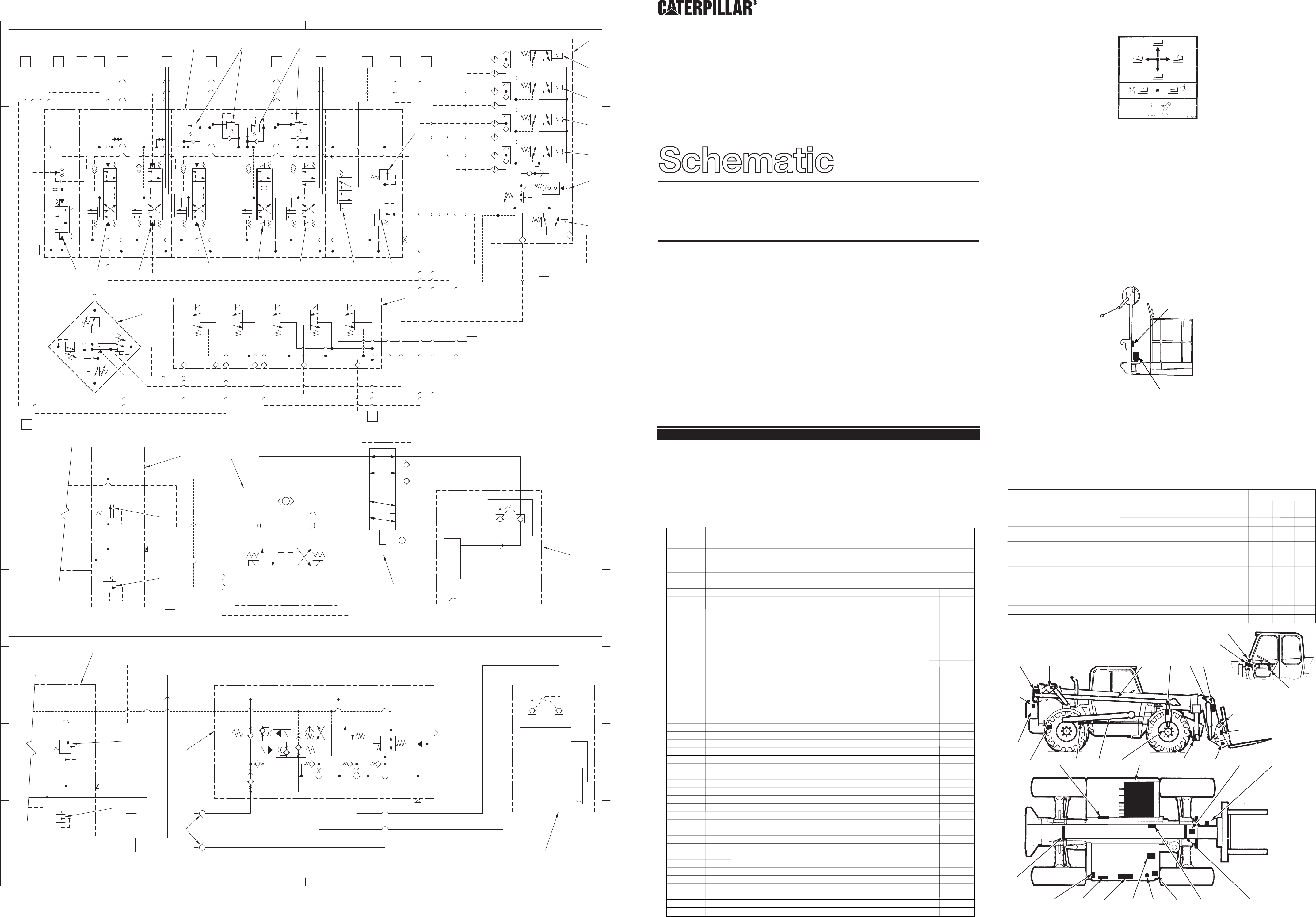
Component Description
Schematic Location
Component
Item No.
Component Location Table
Separate schematics in this publication are identified as Schematic 1, Schematic 2 and Schematic 3.
Components common to all schematics have the same item number. In Schematic 3, some item numbers are
shown in boxes at the end of some of the hydraulic lines. This provides a reference to the component on
Schematic 1 and Schematic 2 that connects to these lines. The schematics have borders and grids to locate the
components. Identify both the cross reference and the number on the schematic from the following table.
No.1
No.2 No.3
Introduction
This publication shows the hydraulic system schematics for machines equipped with the joystick film illustrated
below.
If the film for the joystick control on the machine you are operating is not the one shown above, refer to Hydraulic
Schematic Form No. RENR3473. For full details of the control arrangements refer to Operation & Maintenance
Manual SEBU7370.
140-7909 Film (Boom Control). Installed on machines equipped with a Type A control arrangement.
TH62 Machines
Frame leveling is not an option on these machines. TH62 machines can be equipped with an optional powered
tow hitch attachment which is raised and lowered by a cylinder. This attachment uses valve (59), and the same
instrument panel switch and circuits as frame leveling.
Component Location Illustration of the Access Platform (Swivel)
g500174
40
41
K
J
I
H
G
F
E
D
C
B
A
K
J
I
H
G
F
E
D
C
B
A
87
6
5
432
1
87
6
5
432
1
SCHEMATIC 3
36
16
11
13
5
15
38
38
34
35
30
20
21
22
23 24
25 27
37
1
2
3
4
26
27
P1
P2
26
27
31
TOWBTIP TOWA
BR
LS2
LS1
TO TRAILER BRAKES
BL
JBL
BR
JBR
TL
JTL
JTR
TR
A2
P2
A1
P1 B2
B1
X1
X2
T
Y
26
TH62 HYDRAULIC TOW HITCH, TIPPING VALVE AND TRAILER BRAKING
TH62 HYDRAULIC TOW HITCH/DIVERTER
TH63 AND TH83 ACCESS PLATFORM TYPE 'A' CONTROL ARRANGEMENT
MC
31
36
30
42
44
44
44
45
T
JS
PT
27
39
17
48
49
50
51
52
53
54
55
56
17
57
58
58
17
59
60
18
19
47 Stabilizer Cylinder (if equipped) - F10 -
48 Control Valve (access platform - if equipped) - - A8
49 Solenoid Valve (boom lower) - - A8
50 Solenoid Valve (boom raise) - - A8
51 Solenoid Valve (boom retract) - - B8
52 Solenoid Valve (boom extend) - - B8
53 Solenoid Valve (boom speed) - - B8
54 Solenoid Valve (on/off) - - C8
55 Control Valve (lock out) - - D6
56 Control Valve for Tow Hitch (if equipped) - - F3
57 Diverter Valve for Tow Hitch (if equipped) TH62 Only - - H6
58 Tow Hitch Cylinder (if equipped) TH62 Only - - G8/K8
59 Valve for Tow Hitch/ Tip/Trailer Braking (if equipped) TH62 Only - - J3
60 Couplers (quick disconnect - if equipped) - - K3
Component Location Table (Continued)
Component Description
Schematic Location
Component
Item No.
No. 1 No. 2 No. 3
Component Location Illustration
14
57, 58
60
13
4
12
42, 43 6
5
30
37
7, 8
28
35
11 10
34
38
46, 47
29
9, 15
3
31-33, 55
17- 27, 45 36
16 56, 59 2
1
44
48-54
39
1
2 3 4 5 6
7
8 9
10
11
A
B
C
D
E
F
G
H
11
10
98
7
6543
21
H
G
F
E
D
C
B
A
A
B
C
D
E
F
G
H
1 2 3 4 5 6
7
8 9
10
11
H
G
F
E
D
C
B
A
11
10
98
7
654321
1
2 3 4
5
6
7
8
9
10
11
12
13
14
15
16
20
21 22 23 24 25
26
27
30
31
32
33 34
35
36
37
38
1 2 3 4
10
11
12 13
5 6
14
28
7
8
9
15
29
16
20
21
22 23 24
25
26
27
37
35
34
33
32
31
36
38
30
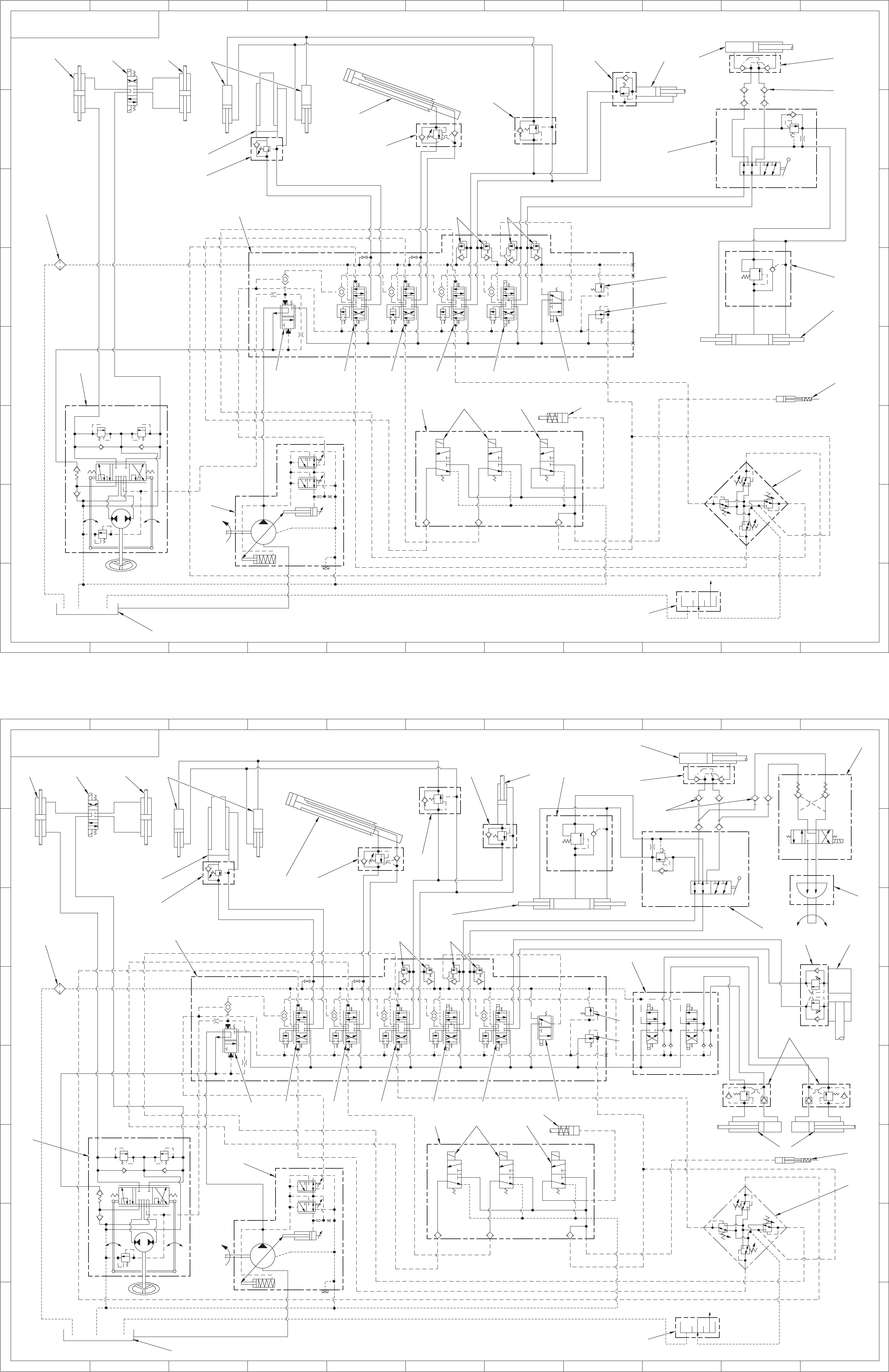
SCHEMATIC 2
SCHEMATIC 1
B2
B1 X1
X2
Y
T
1
2
3
4
1
2
3
4
Y
T
B2
B1
X1
X2
BASIC MACHINE EQUIPPED WITH TYPE 'A' CONTROL ARRANGEMENT
MACHINE EQUIPPED WITH STABILIZERS, THREE AUXILIARY HYDRAULIC SERVICES AND
TYPE 'A' CONTROL ARRANGEMENT
39
28
29
39
40
41
42 43
44
45
46
47
17
18 19
17
18
19
